10
WHITE
AXMINSTER
W
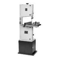
Identification and Parts Description...
Upper blade The upper blade guide height clamp is a butterfly nut and coach bolt
guide height arrangement that clamp through the guide mounting leg and the main saw
clamp frame. So, loose it will allow the mounting guide leg to be moved up and
(See fig 4a) down, tightened it will clamp the leg in position against the frame.
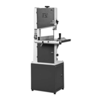
Saw table, tilt The saw table is mounted on the tilt quadrant, which is, in turn mounted in the
assembly quadrant housing and secured via a coach bolt and butterfly nut arrangement.
and scale Loosening the butterfly nut allows the table to be tilted up to 45 degrees
(See fig 6) clockwise. There is an adjustable bolt with a lock nut, screwed into the
underside of the table, which acts as a pre-set stop when bringing the table
back to the level position. There is a scale and pointer attached to the rear of
the quadrant and the housing to measure the angle to which the table has
been tilted. There are two slots machined in the table to accept the slide of
the mitre fence.
Saw table insert The saw table insert fits into the round recessed groove in the centre of the
(See fig 9) table. It not only fills the round void, it also supports the workpiece below the
saw in order to minimise ‘breakout’ from the sawcut. The table insert that is
supplied is for general work, and as such has a fairly wide slot, to allow the
fibre strands from general redwoods and whitewoods to be carried through
by the saw blade. Alternative table inserts should be made when carrying out
very fine work, where the breakout must be kept to a minimum.
Lower blade The lower blade guide assembly is mounted on the main saw frame below the
guide and table, it mounts the rear thrust bearing and two side guide rods that keep the
guard blade stable (straight and untwisted) below the table during the sawing
(See figs 10 & 11) operation. The lower guard is a red plastic enclosure that screws to the guide
assembly, and shields the blade between the underside of the table and the
top of the lower saw wheel compartment.
Fence guide rail The fence guide rail is a metal extrusion that is bolted onto the saw table with
(See figs 1a & 7) 4 hex bolts and washers. The fixing locations in the guide rail are slots, which
allow the angle of incidence between the table and the guide rail to be
adjusted; to enable the guide fence to be set square to the table. There is a
ruler scale set in the guide rail to aid the setting of the guide fence.
NOTE. The guide fence rail should always be fitted and securely
fastened to the saw table, even if it is not properly set up for the fence.
This is to help maintain the stability of the saw table in the area of the
slot which is cut through the table to allow the blades to be fitted.
Guide fence An extruded aluminium assembly primarily consisting of the main mounting
(See fig 2a) body and the blade. The blade is bolted to the top of the main body. The main
body is shaped to fit over the fence rail and mounts the clamping handle. The
clamping handle is attached to a torsion bar which is fed through the blade of
the guide and acts on the rear clamp, pulling it tight against the back rail
through the lever action of the clamp handle. There is a fixed measurement
scale mounted on the fence rail. On each side of the main body is an aperture
through which this scale can be read. Mounted in each aperture is an
adjustable index, to enable the measurements to be zeroed.