23
Optional Wheel Mobility Kit (508207)
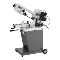
The optional wheel kit provides mobility for the
Hobby bandsaw. To assemble follow the instructions
below:
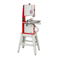
Step 1 Locate the wheel mobility assembly (J), four
M6 bolt, nuts, washers and lifting handle bracket
(K). Lineup the slotted holes in the mobility wheel
bracket (J) with the four slotted holes in the two front
leg supports and secure using the M6 bolts, nuts and
washers (see figs 32-33).
Fig 32-33
J
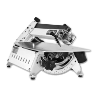
Step 2 Locate the lifting handle bracket (K) and two
M8 coach bolts,nuts and washers (G-H). Remove the
two coach bolts from the right support leg to the
rear of the stand assembly, place safely aside (see fig
34). Line up the four holes in the handle bracket (K)
with the four holes in the stand assembly and secure
in place using the four coach bolts, nuts and washers
(G-H), this includes the coach bolts you removed
earlier. (See figs 34-35)
Fig 34-35
Removed coach bolts
from the support leg
KE G
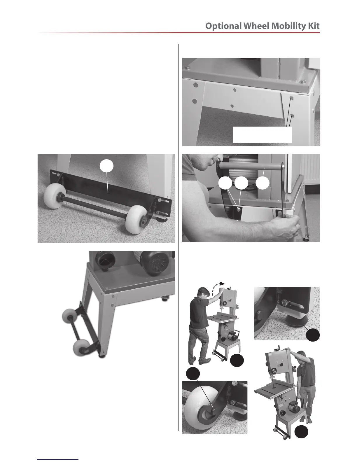
• Lift up the saw (a)
• Push wheels in to engage the up position (b)
and lower the bandsaw.
• Bandsaw feet is now raised of the ground (c)
• Bandsaw being moved to a new location (d)
b
a
c
d
 Loading...