Your saw is packed in the box partially assembled.
This is to ensure that the components are inserted
in the correct positions. For example, the the blade
is fitted, the securing bolt for the tilt mechanism is
inserted in the tilt quadrant with the washer and the
locking butterfly nut threaded on to the bolt, etc.
Please make careful note of the positions of the
various components if you have cause to
disassemble, whilst putting the machine together.
Take all the easily removable items out of the box,
tip the box up so that the base of the saw is to the
ground, remove all the polystyrene packaging from
around the saw (open both sides of the box?) then
“corner walk” the saw out of the box.
If this is still awkward, split the top of the box, fold the
box material flat on the floor, and “wriggle” the saw
off the cardboard. (The best method of moving the
saw is with a ‘hug’ lift through the neck of the saw,
holding the saw back against your body and lifting
by straightening your legs).
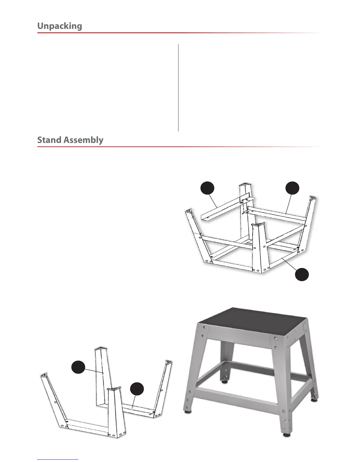
Locate and identify the 4 leg brackets (B), the upper
short struts (C), lower short struts (D), the upper long
struts (E), the lower long struts (F) and M8 x 18mm
coach bolts, washers and nuts(G & H).
Using the M8 coach bolts, nuts and washers bolt
together two legs (B) and one upper short strut (C),
‘finger tighten’ at this time, see fig 1.
When the two frames have been assembled,
select one, turn it upside down on a flat surface and
loosely bolt one of the ‘lower short strut’ (E) in place,
(see fig 2). Attach the other frame and bolt the
remaining strut (E) for the other side. Repeat the
procedure for the lower support struts (D-F).
When all the components are assembled, turn the
stand upright. Using the flat surface as a reference,
tighten up all the nuts, turn the stand on its side and
insert one of the four thread rubber feet (A) into one
of the four pre-drilled holes to the ends of the leg
brackets (B). Tighten in place with a M8 washer and
nut (H). Repeat for the remaining feet. Upright the
frame and stand it on the floor, see fig 3.
B
C
F D
E
Fig 01
Fig 02
Fig 03
 Loading...