ASSEMBLY
14
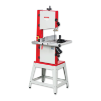
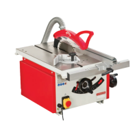
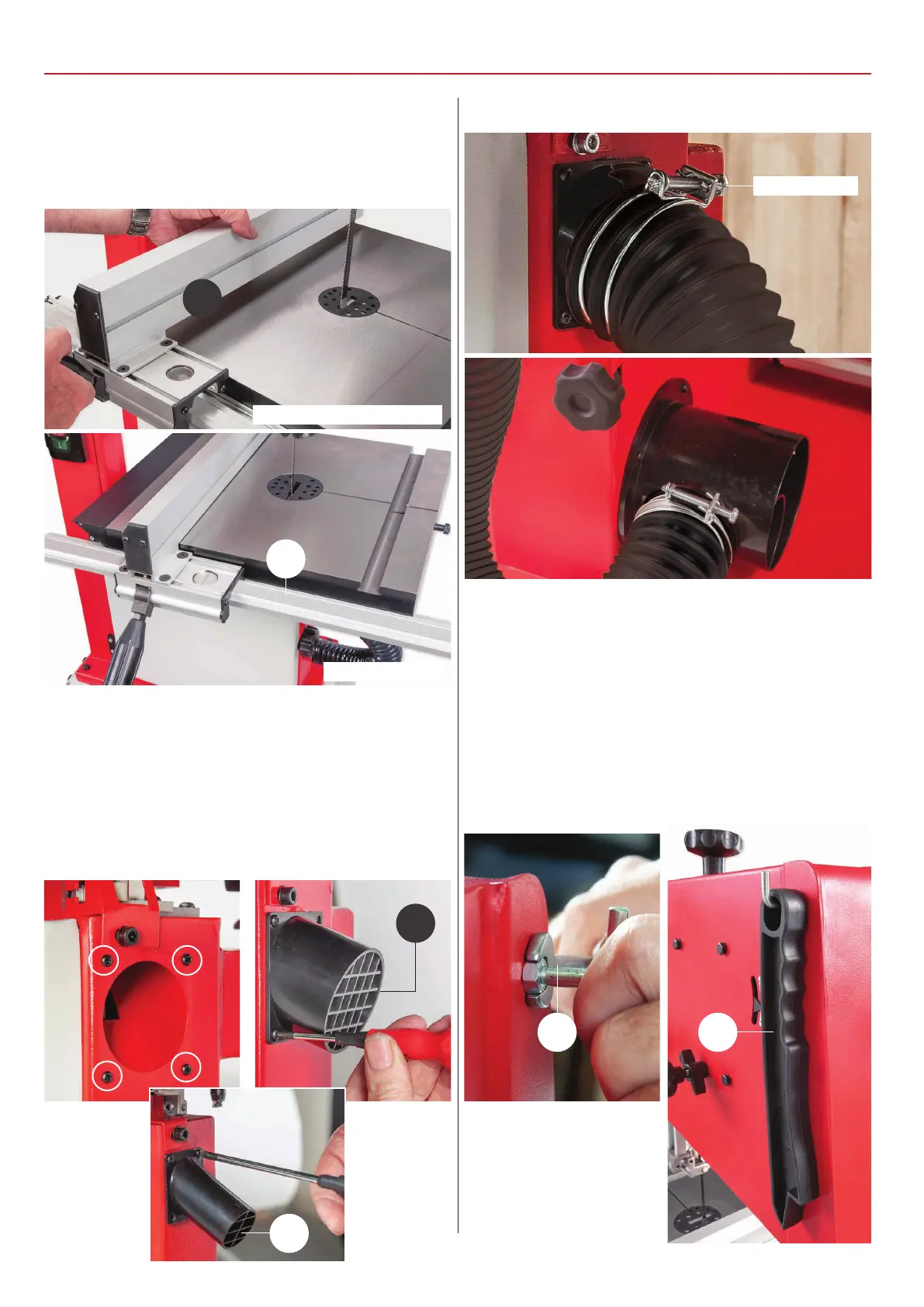
2) Locate the guide fence assembly (4), lowering the fence
down over the fence rail (3) and press down the locking lever
to secure the fence in position, see fig 41-42.
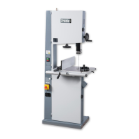
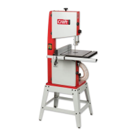
1) Find the extraction port (5), flexible hose and retaining clips
(7). Remove the four Phillips screws around the extraction
outlet beneath the table. Line up the holes in the extraction
port (5) and secure with the Phillips screws, see fig 43-44-45.
Fig 41-42
Extraction Port & Hose Assembly
Fig 43-44-45
4
3
5
5
Fig 48-49
Fig 46-47
2) Place a retaining clip over the end of the hose (7), slide the
hose over the port (5) and tighten the clip. Repeat for the lower
extraction port, see fig 46-47.
3) Locate the angled pin and nut (8) and push stick (9). Screw
the nut onto the threaded pin then screw the pin into the
threaded hole to the rear of bandsaw and tighten with a
spanner. Slot the push stick (9) over the pin, see fig 48-49.
8 9
Retaining clip
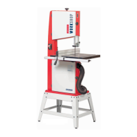
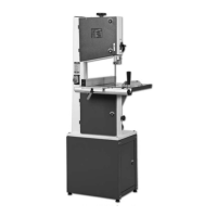
Model AW1950B
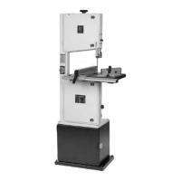
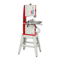
Model AW2305B, AW2606B
 Loading...