• Horizontal pipe with the display facing right as seen from the air inlet (Position 2)
Example: When the MCF is mounted on horizontal piping with the display unit
facing to the right as seen from the air inlet, the instantaneous flow
rate deviation is 1.5 %FS ±1 digit or less as compared with the accura-
cy in the normal position at 0.3MPa.
0.5 %FS / 0.1 MPa ✕ 0.3 MPa = 1.5 %FS
Note: Maintenance mode settings table (page 31, for error correction)
• Horizontal pipe with the display facing left as seen from the air inlet (Position 3)
Example: When the MCF is mounted a horizontal piping and the display unit
looks to the left from the air inlet, the instantaneous flow rate devia-
tion is -1.5 %FS ±1 digit or less as compared with the accuracy in the
normal position at 0.3MPa.
-0.5 %FS / 0.1MPa ✕ 0.3 MPa = -1.5 %FS
Note: Maintenance mode settings table (page 31, for error correction)
Handling Precautions
• When the MCF is mounted on horizontal piping with the display facing to
the right or left side as seen from the air inlet, we recommend setting the
low flow cutoff at 5 (±5 % of the full scale flow rate) or less. If no low flow
cutoff is set, the integrated value might accumulate even without an air
flow.
• Horizontal pipe with the display facing downward and vertical pipe (Positions 4, 5)
The characteristics of the MCF do not change as compared with the normal posi-
tion. However, if the MCF is mounted on horizontal piping with the display unit
downward, accuracy might decrease due to accumulated moisture, mist or dust
from the air.
● Filter
•If there is a possibility of foreign matter entering the device, install a filter,
strainer or mist trap upstream capable of eliminating foreign matter larger than
1 µm in diameter.
• If an oil mist can be expected frequently, be sure to install a mist separator.
Model number: MFF25S / MFF25L
Specifications sheet No. CP-SS-1824E
• Inspect and replace the filter periodically.
8
Chapter 3. MOUNTING AND WIRING
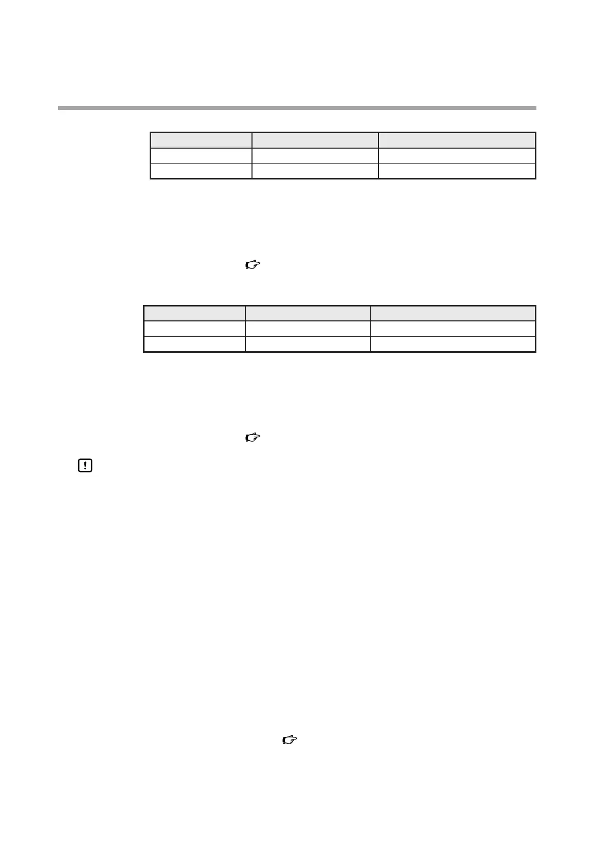
Operating pressure range
Flow rate range Instantaneous flow rate deviation
0 to 1 MPa5 to 100 % of full scale flow rate 0.5 %FS per 0.1MPa ±1 digit or less
-0.07 to 0 MPa 5 to 100 % of full scale flow rate 0.5 %FS per 0.01MPa
±1 digit or less
Operating pressure range
Flow rate range Instantaneous flow rate deviation
0 to 1 MPa5 to 100 % of full scale flow rate -0.5 %FS per 0.1MPa ±1 digit or less
-0.07 to 0 MPa 5 to 100 % of full scale flow rate -0.5 %FS per 0.01MPa
±1 digit or less