9
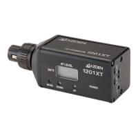
⑱ MIC Connector/Locking Ring
This 3-pin XLR connector is the microphone input. Any low impedance microphone
with a corresponding connector may be plugged here. Once the microphone is plugged
into the 35XT, the locking ring should be rotated clockwise unl snug. To remove the
microphone, rst rotate the locking ring counterclockwise and then pull the micro-
phone away while pressing the XLR release.
⑲ MIC Input LEVEL Control
This enables you to adjust the input level of the connected microphone. Using the sup-
plied tool, turn the orange dial clockwise to increase, or counterclockwise to decrease
the input level.
⑳ LCD Display
The LCD display shows the following informaon:
TV Ch – Transmit Channel Number (i.e. 30 – 01, 31 – 12, 33 – 47)
The TV – Transmit channel display is made of two parts. The rst two digit
number is the actual TV channel (30-33) and the second two digit is the
transmit channel number (01-47).
Baery level by 3-bar indicator (3 bars = High, 1 bar = Low)
AF (Audio Frequency) level by 4-bar indicator (4 bars = High, 1 bar = Low)
To change the channel number, use the p of the tool provided and press the UP or
DOWN buon unl the desired channel number is shown on the LCD Display. Keep the
buon pressed to fast forward the channel numbers.