EasyManua.ls Logo

B2 HVA45TD - User Manual

Default Icon
106 pages
Print Icon
To Next Page IconTo Next Page
Loading...
HVA Family
HVA28 | HVA34-1 | HVA45
and corresponding TD models
User Manual
Ultra-compact, universal
VLF High Voltage Testing Set with Tan Delta
Firmware V2
ENGLISH
DHV0086 Rev06
b2 electronic GmbH
Riedstrasse 1
6833 Klaus
Austria
T +43 (0) 5523 57373
F + 43 (0) 5523 57373-5
www.b2hv.at
info@b2hv.at
Subject to alterations.
Errors excepted.
Illustrations are not binding.
ZERTIFIZIERT
TÜV AUSTRIA CERT GMBH
EN ISO 9001
ZERTIFIKAT NR. 20 100 92003758
Question and Answer IconNeed help?

Do you have a question about the B2 HVA45TD and is the answer not in the manual?

Summary

2 Safety

2.1 General Safety

General safety advice and notice.

2.2 Work Safety

Details electric shock hazard and safety precautions.

Authorized Personnel Only

Restricts access to the test area.

2.4 Operator Qualifications

Specifies required qualifications for operators.

3 General Description

3.1 Technical Specifications

Lists technical data for HVA28TD1 and HVA281.

4 Design and Construction

4.1 Control Elements

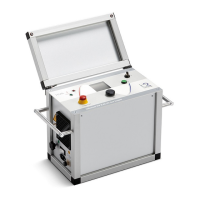
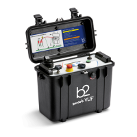
Describes front panel components.

4.3 Instrument Setup

Guides through initial instrument setup.

4.3.1 Setup

Steps to configure the instrument.

Test Modes

Details manual and automatic test modes.

Output Modes

Describes available output modes (DC, VLF, etc.).

Arc Management Modes

Explains how faults are managed.

5 Test Procedure

5.1 Equipment setup

Steps for setting up the equipment.

5.1.1 Connection Diagram: VLF withstand test

Wiring diagram for VLF withstand test.

5.1.3 Connection Diagram: Vacuum Bottle Test

Wiring for vacuum bottle test.

5.2 Manual Test Mode

Guide to performing manual tests.

5.2.1 Setting Report Details

Steps to configure report information.

5.2.2 Manual Test Parameters

Setting parameters for manual tests.

MS1: Setup

How to set waveform, frequency, duration.

MS2: DUT Setup

How to select the Device Under Test.

MS3: SETUP Test Type

How to select the test type.

MS4: SETUP Arc Management Mode

How to set arc management mode.

MS5: Timer

How to set test duration.

5.2.3 Running a Manual Test

Steps to execute a manual test.

MR1: Start New Test

How to start a new test.

MR2: Start Manual Mode

How to select manual mode.

MR4: START Test

How to initiate the test.

MR6: HV Activation

How to activate high voltage.

MR9: Test

The test execution phase.

5.3 Automatic Test Mode

Guide to performing automatic tests.

5.3.2 Configuring Auto Test Sequence on the HVA Unit

Detailed steps for configuring auto test sequences.

NS10: Test Type

How to select test type.

NS15: Arc Management Mode

How to set arc management for VLF tests.

5.3.3 Configuring an Auto Test Sequence on the HVA Unit

Steps to configure an auto test sequence.

AS05: Arc Management Mode

Setting arc management mode.

5.3.4.1 Running an automatic test - Detailed Steps

Detailed steps for running automatic tests.

AR7: HV Activation

How to activate high voltage.

AR9: Test

The test execution.

5.4 Interrupting a Test

Procedures for stopping a test.

5.5 Discharge Status

Explains the discharge status flow.

6 Tan Delta

6.2 Equipment Setup

Setup for Tan Delta testing.

6.2.1 Connection Diagram: VLF withstand test with Tan Delta

Wiring for VLF withstand test with Tan Delta.

6.2.2.1 Option with corona shield

Setup for using corona shields.

6.2.2.2 Option with corona shield guard on far end

Setup for using corona shields and guard on far end.

6.3 Tan Delta Test

Procedures for running Tan Delta tests.

6.3.1 Running a Manual Test with Tan Delta

Steps to run a manual Tan Delta test.

TD4: Start Test

How to start the Tan Delta test.

TD5: HV Activation

How to activate high voltage for Tan Delta.

TD8: Test

The Tan Delta test execution.

7 Reporting

7.1 Report Type

Explains basic vs. extended reports.

7.2 Report Activation

How to enable/disable reporting.

7.3 Report Naming Instructions

How to name reports.

7.4 Manage Reports

How to manage saved reports.

8 Disconnection Procedure

8.1 Disconnection Diagram - Normal Conditions

Diagrams for normal disconnection.

8.2 Disconnection Diagram - System Failure

Diagrams for disconnection during system failure.

9 Instrument Care

B2 HVA45TD Specifications

General IconGeneral
BrandB2
ModelHVA45TD
CategoryTest Equipment
LanguageEnglish

Related product manuals