4
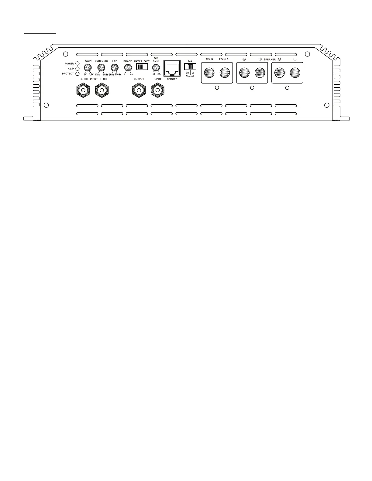
Panel layout
INPUT LPF (LOW PASS FILTER 20 Hz ~200 Hz, 24 dB/oct)
RCA signal input for left & right channel. Adjusts the cut o point for the low pass crossover
A minimum of 0.2V input signal is required for correct at the frequency chosen.
operation. Using only 1 input will minimize input signal
and amplier will need to be gained as such.
Phase
Variable phase adjustment from 0 ~ 180
POWER & PROTECTION INDICATOR adjusted in accordance with the ampliers gain.
Power LED, blue light shows correct operation,
Protect LED, red light shows general malfunction, faulty master / daisy
connection or thermal protection. Master & Daisy switch for daisy chain link or master mode.
In daisy, the master amplier will route the gained signal to
clip INDICATOR daisy (linked) amplier. The gain on the gaisy is controlled
The LED will light up if signal is clipped. An occastional the master.
ashing light is acceptable, a constant lit diode is not.
Gain daisy
GAIN (5V~0.2v) Fine tuning of the master signal routed to the daisy amp.
Adjusts signal input voltage from the input source While the ordinary gain on daisy amps are disabled, the
to match the ampliers input stage. daisy amp is gain matched by the master, but if there is
0.2 V ~ 5 V is the operational voltage. a slight variance in signal up to +/- 5%, the Daisy gain
Voltages beyond may cause errors or damage to the can equalize it.
input section.
remote
SUBSONIC Remote level control port with clip and voltage output.
Variable subsonic setting from 10 Hz to 50 Hz.
It is highly recommended to set it according to the tuning
Fan
of your subwoofer enclosure to avoid unnecessary strain to Switch selection of the internal fans operational mode.
your sound system. O turns of the fan entirely. Thermal mode will have the
fans kick in at set temperature. On is continious mode
rem in / rem out
REM IN =Switched remote signal to turn on the amplier.
REM OUT = Switched remoute signal ouput. This can be
used for daisy amps or other 12V equipment.
o