SKU 272-0095/FC-30-MN
05
© 2018 Jack-Post Corporation 09/18
MATERIAL PLAN 4 FOOT LONG TABLE 6 FOOT LONG TABLE 8 FOOT LONG TABLE
LUMBER CUT SIZES LUMBER CUT SIZES LUMBER CUT SIZES
Pcs. Length Size Pcs. Length Size Pcs. Length Size Pcs. Length Size Pcs. Length Size
9 8 ft. 2 x 4 14 4 ft. 2 x 4 15 8 ft. 2 x 4 14 6 ft. 2 x 4 16 8 ft. 2 x 4
– – – 3 28 in. 2 x 4 – – – 3 28 in. 2 x 4 – – –
– – – 6 10 in. 2 x 4 – – – 8 10 in. 2 x 4 – – –
LUMBER CUT SIZES LUMBER CUT SIZES LUMBER CUT SIZES
Pcs. Length Size Pcs. Length Size Pcs. Length Size Pcs. Length Size Pcs. Length Size
5 8 ft. 2 x 6 9 4 ft. 2 x 6 9 6 ft. 2 x 6 9 6 ft. 2 x 6 9 8 ft. 2 x 6
2 8 ft. 2 x 4 3 28 in. 2 x 4 2 8 ft. 2 x 4 3 28 in. 2 x 4 2 8 ft. 2 x 4
– – – 6 10 in. 2 x 4 – – – 8 10 in. 2 x 4 – – –
LUMBER CUT SIZES LUMBER CUT SIZES LUMBER CUT SIZES
Pcs. Length Size Pcs. Length Size Pcs. Length Size Pcs. Length Size Pcs. Length Size
1 8 ft. 2 x 10 5 4 ft. 2 x 10 5 6 ft. 2 x 10 5 6 ft. 2 x 10 5 8 ft. 2 x 10
1 12 ft. 2 x 10 – – – 1 8 ft. 2 x 4 1 25 in. 2 x 4 1 8 ft. 2 x 4
– – – – – – – – – – – – – – –
Pcs. Length Size
14 8 ft. 2 x 4
3 28 in. 2 x 4
8 10 in. 2 x 4
Pcs. Length Size
9 8 ft. 2 x 6
3 28 in. 2 x 4
8 10 in. 2 x 4
Pcs. Length Size
5 8 ft. 2 x 10
1 25 in. 2 x 4
– – –
2x4’s
2x6’s
2x10’s
29-1/2"
28-1/4"
11"
28"
9-1/2"
11-1/4"
TABLE
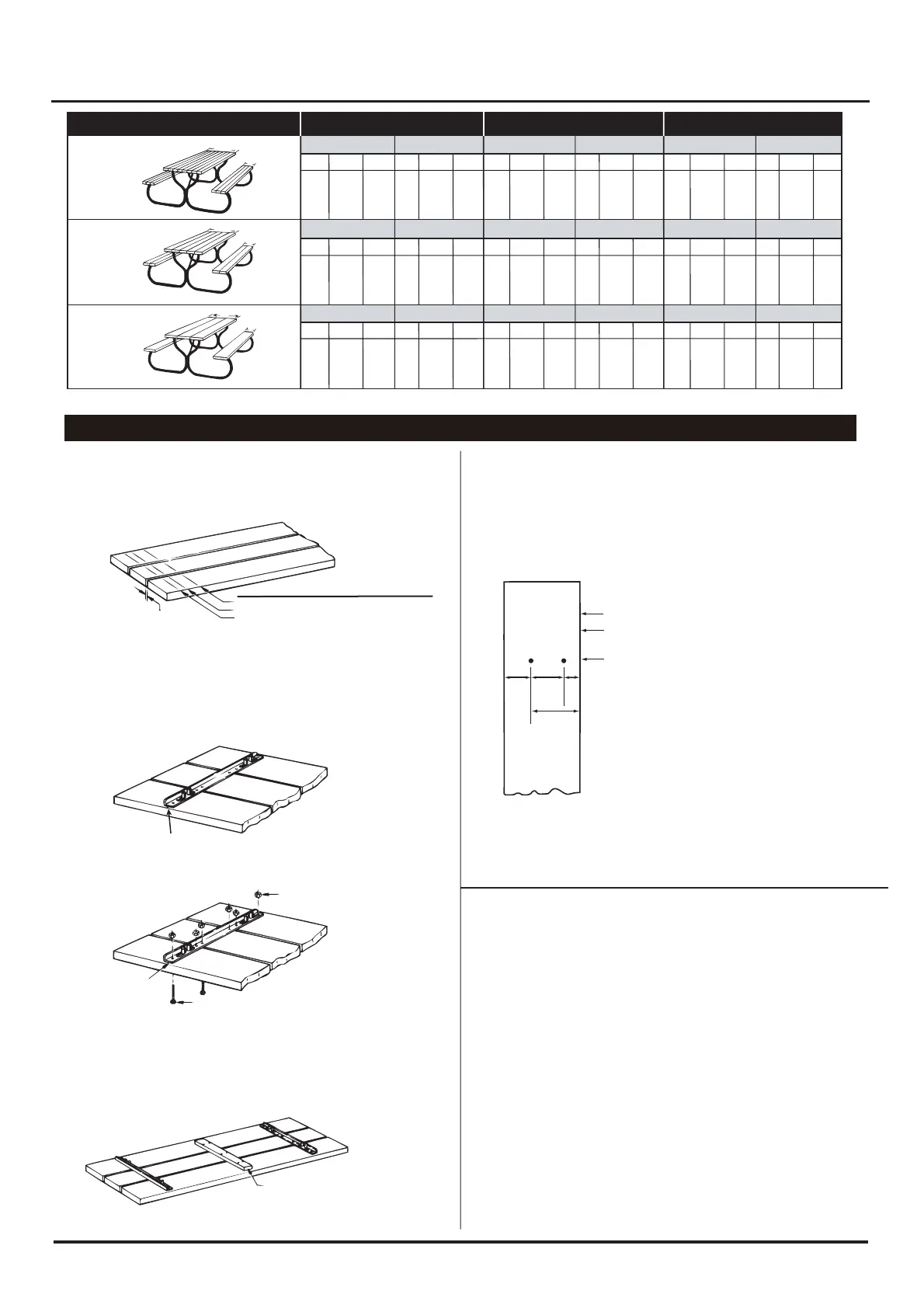
STEP 2 Measure and draw line across boards 4" from one end for 4' table,
6" from one end for 6' table, or 10" from one end for 8' table.
DRAW ONE LINE
AT BOTH ENDS OF TABLE
MAINTAIN 1/4" SPACE
BETWEEN ALL BOARDS
8' TABLE –10" FROM END
6' TABLE – 6" FROM END
4' TABLE – 4" FROM END
STEP 3 Center and mark 6 holes in angle bracket on line drawn in STEP 1,
as shown. Drill 1/4" diameter holes.
STEP 4 Attach angle bracket to top boards with six 2" carriage bolts and
hex nuts, as shown.
2X10’S
STEP 5 Repeat STEPS 2 - 4 for opposite end.
CENTER 25" CLEAT
2" CARRIAGE BOLT (6) EACH SIDE
ANGLE BRACKET
1/4" HEX NUT (6) EACH SIDE
SEAT
STEP 1 Layout two 2" x 10"’s in the length you have chosen.
STEP 2 Measure and draw lin across one board 4" from end for 4' table, 6"
from end for 6' table, or 10" from end for 8' table, as shown.
Locate and drill two 1/4" diameter holes as indicated by drawing below.
DRAW ONE LINE AT BOTH ENDS OF SEAT
4" FOR 4' TABLE
6" FOR 6' TABLE
10" FOR 8' TABLE
6"
3-1/4" 4"
2"
STEP 3
Repeat STEP 2 for opposite end of seat board and for remaining seat board.
FINAL ASSEMBLY
CENTER BRACKET ON LINE AND MARK HOLES
STEP 1 Attach two tubular legs to angle bracket with 2" slotted head screws
and 1/4" hex nuts.
STEP 2 Fasten the two tubular legs together with two 2-5/8" slotted head screws,
fastening brace between legs through hole as shown.
STEP 3 Make sure tubular leg assembly is at a right angle (90º) to the table top.
Bend brace so that it lays at against table top. Locate the point at which hole in
brace contacts the table top and drill 1/4" diameter hole, as shown.
No cleat used on 4' table.
STEP 4 Attach brace to table top with 2" carriage bolt and hex nut as shown.
STEP 5 Repeat STEPS 1 - 4 for opposite end of table top.
STEP 6 Mount benches to leg assemblies with 3-1/4" carriage bolts.
STEP 7 Tighten all bolts.
STEP 1 Layout three 2" x 10"’s in the length you have chosen, best side
down on a at surface, maintaining a 1/4" spacing between boards.
Extra 1/4" carriage bolts can be placed between boards to maintain space.
STEP 6 On 6' and 8' tables, center the 25" x 2" x 4" cleat between the angle
brackets and nail to the table top boards. Before nailing cleat, cover the
mating surface of the cleat with a coat of white glue. See STEP 3A of
2 x 4 instructions.
 Loading...