iii
Unit 8&9 / York Park / Bridgend, United Kingdom / CF31 3TB
+44 (0) 1656 645688 / Fax: +44 (0) 1656 667966 / sales@ruskinn.com /
www.bakerruskinn.com
TABLE OF FIGURES
Figure 1: Concept Rear Connections ................................................................................ 7
Figure 2: Gas Connection Graphic .................................................................................... 8
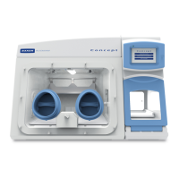
Figure 3: Standard Concept Workstation with SPES Option.............................................. 9
Figure 4: Large Concept Workstation ............................................................................... 9
Figure 5: Right Side Internal View ................................................................................... 10
Figure 6: Left Side Internal View ..................................................................................... 10
Figure 7: Left Side End Panel with Ultrasonic Humidity Option ...................................... 11
Figure 8: Right Side End Panel ....................................................................................... 12
Figure 9: Rear End Panel and Supply Connections ......................................................... 13
Figure 10: Gas and Electrical Connections ..................................................................... 13
Figure 11: Ezee -Sleeves ................................................................................................ 18
Figure 12: Compressed Ezee-Sleeve for Entry ................................................................ 19
Figure 13: Arm inserted into Ezee-Sleeve (Shown with and without Ezee-Sleeve) .......... 19
Figure 14: Foot pedals for right and left glove ports ....................................................... 20
Figure 15: Ezee-Sleeve before vacuum........................................................................... 20
Figure 16: Ezee-Sleeve after vacuum ............................................................................. 20
Figure 17: Glove port cap ............................................................................................... 21
Figure 18: Glove port cap stowage and locator ............................................................... 21
Figure 19: Glove port cap storage location inside workstation........................................ 22
Figure 20: Glove port cap ............................................................................................... 23
Figure 21: Glove Port Locator ......................................................................................... 23
Figure 22: Aquasorb Sachets - Empty and Charged ........................................................ 24
Figure 23: Aquasorb Sachet in Workstation .................................................................... 24
Figure 24: Condensate Plate .......................................................................................... 25
Figure 25: Condensate Output and Tray ......................................................................... 25
Figure 26: Front Screen Pneumatic Connector Disconnection ........................................ 41
Figure 27: Ceiling Panel Thumb Screws .......................................................................... 44
Figure 28: Ceiling Panel Handle and Grab Catch ............................................................. 44
Figure 29: Large Detox Sachet ........................................................................................ 45
Figure 30: Large Catalyst Sachets .................................................................................. 45
Figure 31: Gloveport Sleeves .......................................................................................... 45