PLC Mode Description 10-11MN765
10.8 PLC Mode as a Modified Process PID Mode
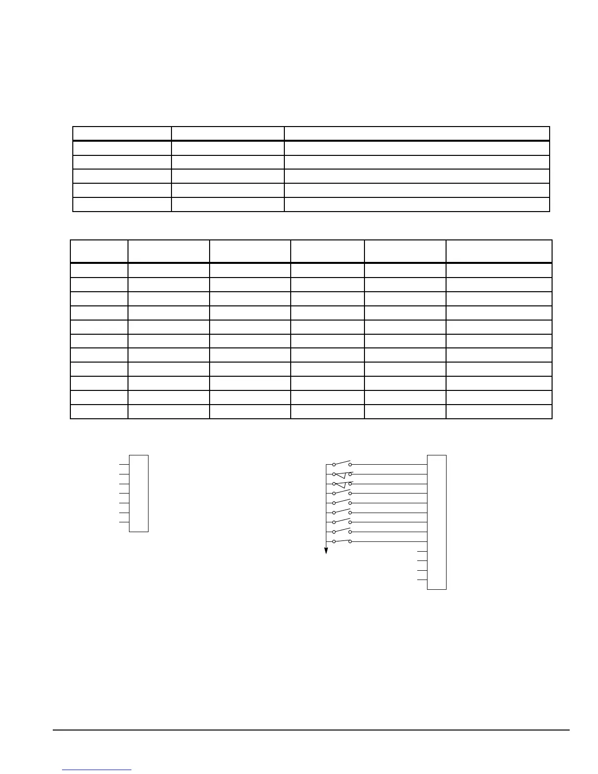
This example shows how the PLC Mode as a modied Process PID Mode.
Initialization:
Parameter Value Comment
P1401 PLC PLC operating mode selected
P1501 PLC Digital Output 1 Set by PLC Mode Logic
P3431 10 Comparator A monitors absolute speed demand (P10)
P3432 20% Comparator A’s constant (12 Hz for 60 Hz max)
P3440 3.00 sec Timer A set for 3 seconds
PLC Mode configuration parameters:
Parameter
Number
Parameter Dec
Value
Byte 3 Condition Byte 2 Logic Byte 1 Condition Byte 0 Action
P3401 076.000.000.040 Comp A (76) OR (0) False (0) A (40)
P3402 050.000.000.020 Input 1 (50) OR (0) False (0) Forward (20)
P3403 051.000.000.021 Input 2 (51) OR (0) False (0) Reverse (21)
P3404 100.000.000.038 A (100) OR (0) False (0) Torque/Speed (38)
P3405 053.002.100.029 Input 4 (53) XOR (2) A (100) PID (29)
P3406 054.000.055.018 Input 5 (54) OR (0) Input 6 (55) Jog Enable (18)
P3407 054.000.000.006 Input 5 (54) OR (0) False (0) Jog Forward (6)
P3408 055.000.000.005 Input 6 (55) OR (0) False (0) Jog Reverse (5)
P3409 056.000.000.023 Input 7 (56) OR (0) False (0) Reset (23)
P3410 057.000.000.050 Input 8 (57) OR (0) False (0) Start Timer (50)
P3411 086.000.000.019 Timer A (86) OR (0) False (0) Fault (19)
User Analog Return
Analog Input 1
Analog Ref. Power +
1
2
3
4
5
6
7
J1
Analog Input 2+
Analog Input 2-
Analog Output 1
Analog Output 2
Enable
J2
Digital Output 1 + (Collector)
Digital Output 1 - (Emitter)
Digital Output 2 + (Collector)
Digital Output 2 - (Emitter)
Enable
Forward Enable
Reverse Enable
PID
Jog Enable
Jog Forward
Jog Reverse
Fault
Fault Reset
Digital Input 1
Digital Input 2
Digital Input 3
Digital Input 4
Digital Input 5
Digital Input 6
Digital Input 7
Digital Input 8
8
17
9
10
11
12
13
14
15
16
18
19
20
*
*Note: Remove factory jumper from J2-8 and J3-24 before connecting switch at J2-8.
See recommended tightening torques in Table A-2.
See Figure 5-4 for connection information.
The Parameter Dec Value column can be used when entering the PLC conguration parameters at the keypad (parameters
are shown as decimal long values - byte3.byte2.byte1.byte0).
For this mode Enable is active.
Use of logical variables A, B, C or D allows for complex PLC logic.
Variable “A” is set based on the outcome of a comparator and then used as an input condition for the torque/speed select
and PID actions.




 To Next Page