SETTING THE CRIMPING DIAMETER MS
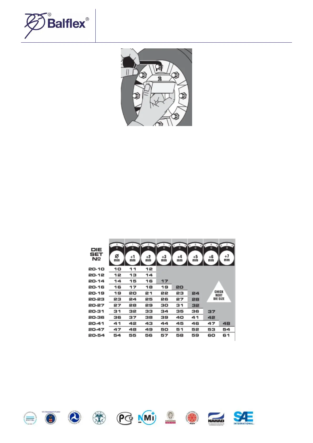
From the crimping diameter chart on the electric box door you can see the die set numbers and the corresponding
crimping ranges. The upper section of the chart shows the corresponding dial position for each crimping diameter in
the columns. Crimping diameters in the grey zone of the chart are not recommended. The crimping diameter dial has
been calibrated at the factory so that when the dial is set at 0.0, the resulting diameter will be the minimum diameter
of the die set installed, i.e. with die set Nº P20/16 the crimping diameter will be 16 mm, Nº P20/19 gives a diameter
of 19 mm etc. Each full turn clockwise of the adjusting knob of the dial will add 1 mm to the crimping diameter. Each
division on the measuring scale corresponds to 1/100 mm.