www.balluff.com
Construction and function Installation and connection
2english
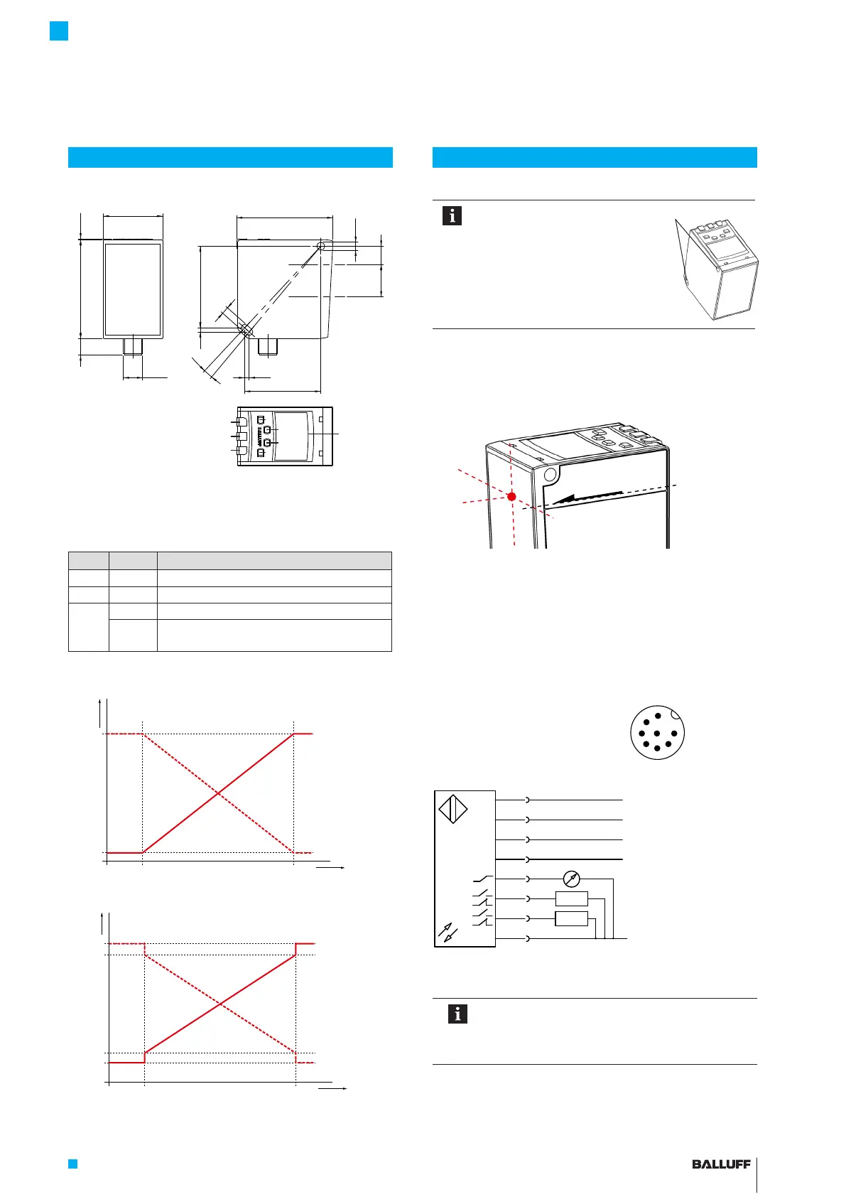
Dimensions
37
10.1
M12x1
61.7 0.5
11.420.2
3.1°
50.82.5
2.9
47.4
60
Ø
5
4,5
6
1
2
3
5
4
7
8
1 ESC button
2 Up button
3 Down button
4 SET button
5 5-digit / Multi Display
6 LED 1
7 LED 2
8 LED 3
LED Color Function
1 Yellow Output Q1 is active
2 Yellow Output Q2 is active
3 Red Measurement is outside the measuring range
Green Sensor is switched on, measurement is
within the measuring range
Output function
MIN
0.2
0
10
V
MAX
mm
Distance
Analog output
MIN
0
20.0
4.0
3.5
20.5
mA
MAX
mm
Analog output
Distance
The sensor can be fastened
through two holes in the body (1)
with screws, tightening nuts, and
washers. Only fasten the sensor
to the reference surface marked
with A!
A
1
In case of direct fastening, observe an adjustment angle of
±1.5°. The measurement refers to the front surface of the
laser optics (see figure).
Ref.
1. In a de-energized state, connect the M12 connector to
the sensor.
2. Connect the cable to the supply voltage and I/O as
intended for the respective model.
3. Aim the sensor's laser point at the target and fasten
the sensor in a suitable holder with two screws (e.g.
M4×45, with tightening nuts and washers).
Plug and porting configuration
(Top view of the plug on the BOD)
+24 V ±20 % (U
B
)
RS485 –
RS485 +
Multifunction input (IN)
Analog Out (QA)
Q1 (≤ 100 mA)
Q2 (≤ 100 mA)
0 V
Colors
:Pin:
1)
1
5
4
8
6
3
2
7
WH
GY
YE
RD
PK
GN
BN
BU
1) In conjunction with the plug connector specified under
accessories
The measurement function is available just a few
seconds after the device is switched on. To
achieve full accuracy, a warm-up phase of
approximately 20 minutes must be observed.
8
7
1
2
5
6
4
3
BOD 37M-LPR02-S115
Photoelectric Sensors – Laser Distance Sensor
 Loading...