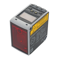
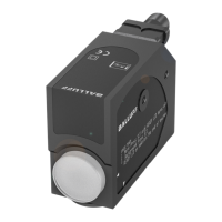
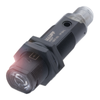
EasyManua.ls Logo

Balluff BOS 18K Series - User Manual

Balluff BOS 18K Series
3 pages
Print Icon
To Next Page IconTo Next Page
Loading...
BOS 18Kx-xx- SERIES
INSTRUCTION MANUAL
CONTROLS
OUTPUT LED (BOS 18K…PD/PE/XA/QC/QD/RE/TB/FR/1N1R, BLE
18K..)
The yellow LED ON indicates that the NO output status is closed.
STABILITY LED (BOS 18K...PD/PE/QC/QD/FR, BLE 18K...PP)
The green LED ON indicates that the received signal has a reserve
greater than 30% compared to the output switching value.
POWER ON LED (BLS 18K...1P)
The green LED indicates that the sensor is operating.
POTENTIOMETER (BOS 18K...QD/PD/PE/TB/FR, BLE 18K...PP)
The potentiometer can be used to adjust sensitivity; the operating
distance increases turning the potentiometer clockwise.
WARNING: The potentiometer rotation is limited to 270° by a
mechanical stop.
Do not apply excessive torque when adjusting (max 40 Nmm).
INSTALLATION
The sensor can be fixed by means of the M18x1 threaded body through a 18mm
hole, using the specific washer and the two CH.24 nuts enclosed (1.5Nm maximum
tightening torque).
Alternatively, the sensor can be mounted
through the two housing’s holes using two
screws (M3x22 or longer) and washer.
Amongst the various possible solutions, we
suggest to choose the combination that offers
the best visibility of the signalling LEDs and the
easiest access to the potentiometer.
Wide range of accessories available: 22mm
nuts, h=8mm, (2Nm maximum tightening
torque) guarantee an improved torque and
various orientable fixing brackets ease the
sensor positioning (please refer to the
accessories listed in the general catalogue).
The operating distance is measured from the front surface of the sensor lens.
Only diffuse type: To improve the detection, the object has to be moved closer or further
away from the front surface of the sensor lens.
In case of lateral translation, the object must move as indicated in the figure.
CONNECTIONS
The connections are complaint to the EN 60947-5-2.
BOS/BLS
+
10 … 30 Vdc
NC OUTPUT
BROWN
1
WHITE
2
BLACK
4
BLUE
3
NO OUTPUT
0 V
BLE
+
10 … 30 Vdc
TEST +
BROWN
1
WHITE
2
BLACK
4
BLUE
3
TEST -
0 V
M12 CONNERCTOR
2
3
1
4
DIMENSIONS
24
N°.2 Ø3.8
4
=
2.5
=
4
=
3.8
2
STABILITY LED
10
15
M18x1
1.5
14
3.5
24
3.5
1.5
44
2
=
3.8
14
12
10
14.5
.2 Ø3.8
TRIMMER
15
mm
14
=
M18x1
Ø4
25
25
RADIAL VERSION
TRIMMER
OUTPUT LED
STABILITY LED
OUTPUT LED
OUTPUT LED
STABILITY LED
without trimmer
L
X
X1
M O D E L S
with trimmer
X1
X
AXIAL VERSION
L
X
X1
X
X1
CABLE VERSION
=
M12
=
M12
14.5
L
14.5
L
79
43
46
69
42
36
57
42
24
67
43
34
10
without trimmer
M O D E L S
with trimmer
TECHNICAL DATA
BOS 18KF (Axial version) BOS 18KW (Radial version)
Power supply: 10 … 30 Vdc
Ripple: 2 Vpp max.
Current consumption
(output current excluded):
35 mA max.
Outputs: NO and NC; PNP or NPN
Output current: 100 mA max.
Output saturation voltage: 2 V max.
Response time: 0.5 ms (2 ms BLE/BLS)
Switching frequency: 1KHz (250 Hz BLE/BLS)
Indicators: output-LED (yellow) ( BLS)
stability-LED (green) (BOS 18K...QC/QD and BLE)
POWER ON LED (green) (BLS)
Setting: sensitivity potentiometer (BOS 18K...PD/PE/QC/QD/TB, BLE 18K...)
Operating temperature: -25 … 55 °C
Operating distance (typical values): BOS 18KF-...RE: 0.1…5m on R1
BOS 18KF-...QD: 0.1…4.5m on R1
BOS 18KF-...PE: 0…70cm
BOS 18KF-...XA: 0…10cm
BOS 18KF-...PD: 0…40cm
BOS 18KF-...1N1R: 0,5…10cm
BLE/BLS 18KF-...: 0…20m
BOS 18KF-...FR: depends on fiber
BOS 18KF-...TB: 0.1…1,7m on R1
BOS 18KW-...QC: 0.1…3m on R1
BOS 18KW-...PD: 0…40cm
BOS 18KW-...XA: 0…8cm
BOS 18KW-...1N1R: 0…8cm
BLE/BLS 18KW-...: 0…15m
BOS 18KW-...TB: 0.1…1,7m on R1
Emission type: red (660nm) (BOS 18..QC/QD/TB/FR/1N1R) / infrared (880nm) (BOS 18..RE/PD/PE/XA; BLS18..1P)
Ambient light rejection: according to EN 60947-5-2
Housing material: PBT
Mechanical protection: IP67
Connections:
2 m cable 4 mm / M12 - 4 pole connector
Weight: 75 g. max. cable vers. / 25 g. max. connector vers.
SETTING
Setting of BOS 18K...RE
Position the sensor and reflector on opposite sides.
Find the points where the yellow LED (OUT) is switched ON and OFF in
both vertical and horizontal positions and fix the sensor in the centre
between these points.
Setting of BOS 18K...QC/QD/TB
Position the sensor and reflector on opposite sides.
Turn the sensitivity potentiometer to the maximum position.
Moving the sensor both vertically and horizontally, determine the power
on and off points of the yellow LED (OUT) and then mount the sensor in
the middle of the points defined. Optimum operation is obtained when
the green LED (only BOS 18K...QC/QD) is ON and the yellow LED is
OFF.
QC/QD If necessary reduce sensitivity in order to detect
very small targets. In order to improve alignment, repeat
the procedure detailed above whilst progressively
reducing the sensitivity.
TB Turn the sensitivity trimmer counterclockwise until the yellow LED
turns ON (pos.A). Turn slowly the trimmer again clockwise until the
yellow LED turns OFF (Operating condition, pos.B).
Setting of BLE/BLS 18K.../BOS 18…FR (with P/R fibre optics)
Position the sensors on opposite sides.
Turn the sensitivity potentiometer to maximum: moving the sensor both
vertically and horizontally, determine the power on and off points of the
yellow LED (OUT) and then mount the sensor in the middle of the points
defined. Optimum operation is obtained when the green LED is ON and
the yellow LED is OFF.
If necessary, reduce sensitivity using the potentiometer, in order to
detect very small targets. In order to improve alignment, repeat the
procedure detailed above whilst progressively reducing the sensitivity.
Setting of BOS 18K...PD/PE/FR with proximity fibre
Turn the sensitivity potentiometer to minimum: the green LED is ON, the
yellow LED is OFF. Position the target to detect in front of the sensor or
of the fibre terminals. Turn the sensitivity potentiometer clockwise until
the yellow LED turns ON (Target detected state, pos.A).
Remove the target, the yellow LED turns OFF.
Turn the sensitivity potentiometer clockwise until the yellow LED turns
ON (Background detected state, pos.B).
The potentiometer reaches maximum if the background is not detected.
Turn the potentiometer to the intermediate position C, between the two
positions A and B. The green LED must be ON.
Setting of BOS 18K...XA/1N1R
The operating distance range of these sensors is fix. Please consider
this feature when positioning.
TEST FUNCTION (BLS)
The TEST+ and TEST- inputs can be used to inhibit the emitter and
verify that the system is correctly operating.
The receiver output should switch when the test is activated while the
beam is uninterrupted.
The inputs activating voltage range is 10 … 30 Vdc.
Balluff GmbH
Schurwaldstrae 9
73765 Neuhausen a.d.F. Deutschland
Tel.: +49 (0) 71 58/1 73-0
Fax +49 (0) 71 58/50 10
E-Mail: balluff@balluff.de
www.balluff.com
Nr./No. 826 220 D/E
Ausgabe/Edition 1108;
Änderungen vorbehalten/Subject to modification
Ersetzt Ausgabe/Replaces edition 0412
MIN
MAX
A
B
C
Question and Answer IconNeed help?

Do you have a question about the Balluff BOS 18K Series and is the answer not in the manual?

Overview

The Balluff BOS 18Kx-xx- SERIES is a range of photoelectric sensors designed for various industrial automation applications, offering both axial and radial versions, as well as cable and connector options. These sensors are primarily used for object detection, presence sensing, and positioning tasks.

Function Description

The BOS 18Kx-xx- SERIES sensors operate by emitting light and detecting its reflection or interruption. They are available in different operating principles, including diffuse, retro-reflective, and through-beam, catering to a wide range of detection scenarios.

Output LED (BOS 18K...PD/PE/XA/QC/QD/RE/TB/FR/1N1R, BLE 18K..): A yellow LED indicates the status of the NO (Normally Open) output. When the output is closed, the LED is ON.

Stability LED (BOS 18K...PD/PE/QC/QD/FR, BLE 18K...PP): A green LED illuminates when the received signal has a reserve greater than 30% compared to the output switching value, indicating stable operation.

Power ON LED (BLS 18K...1P): A green LED confirms that the sensor is powered and operating.

Potentiometer (BOS 18K...QD/PD/PE/TB/FR, BLE 18K...PP): This feature allows for sensitivity adjustment. Turning the potentiometer clockwise increases the operating distance. A mechanical stop limits rotation to 270°, and excessive torque (max 40 Nmm) should be avoided during adjustment.

Test Function (BLS): For BLS models, TEST+ and TEST- inputs are provided to inhibit the emitter and verify system functionality. The receiver output should switch when the test is activated with an uninterrupted beam. The activating voltage range for these inputs is 10 ... 30 Vdc.

Important Technical Specifications

The BOS 18Kx-xx- SERIES sensors are robust and designed for industrial environments.

Power Supply:

  • Voltage: 10 ... 30 Vdc
  • Ripple: 2 Vpp max.
  • Current Consumption (output current excluded): 35 mA max.

Outputs:

  • Type: NO and NC; PNP or NPN
  • Output Current: 100 mA max.
  • Output Saturation Voltage: 2 V max.

Performance:

  • Response Time: 0.5 ms (2 ms for BLE/BLS models)
  • Switching Frequency: 1KHz (250 Hz for BLE/BLS models)

Indicators:

  • Output-LED: Yellow (BLS)
  • Stability-LED: Green (BOS 18K...QC/QD and BLE)
  • Power ON LED: Green (BLS)

Setting:

  • Sensitivity Potentiometer: (BOS 18K...PD/PE/QC/QD/TB, BLE 18K...)

Environmental:

  • Operating Temperature: -25 ... 55 °C
  • Mechanical Protection: IP67

Emission Type:

  • Red: 660nm (BOS 18..QC/QD/TB/FR/1N1R)
  • Infrared: 880nm (BOS 18..RE/PD/PE/XA; BLS18..1P)
  • Ambient Light Rejection: According to EN 60947-5-2

Housing Material: PBT

Connections:

  • 2 m cable Ø 4 mm
  • M12 - 4 pole connector

Weight:

  • Cable version: 75 g max.
  • Connector version: 25 g max.

Operating Distance (typical values):

  • BOS 18KF (Axial version):
    • RE: 0.1...5m on R1
    • QD: 0.1...4.5m on R1
    • PE: 0...70cm
    • XA: 0...10cm
    • PD: 0...40cm
    • 1N1R: 0.5...10cm
    • BLE/BLS: 0...20m
    • FR: depends on fiber
    • TB: 0.1...1.7m on R1
  • BOS 18KW (Radial version):
    • QC: 0.1...3m on R1
    • PD: 0...40cm
    • XA: 0...8cm
    • 1N1R: 0...8cm
    • BLE/BLS: 0...15m
    • TB: 0.1...1.7m on R1

Usage Features

The sensors are designed for straightforward installation and adjustment.

Installation:

  • M18x1 Threaded Body: Can be fixed through an Ø 18mm hole using the provided washer and two CH.24 nuts (1.5Nm max tightening torque).
  • Housing Holes: Alternatively, the sensor can be mounted using two M3x22 (or longer) screws and washers through the housing's holes.
  • Optimal Positioning: It is recommended to choose a mounting solution that offers the best visibility of the signaling LEDs and easy access to the potentiometer.
  • Accessories: A wide range of accessories, including 22mm nuts (h=8mm, 2Nm max tightening torque) and orientable fixing brackets, are available for improved torque and flexible sensor positioning.
  • Operating Distance: Measured from the front surface of the sensor lens.
  • Diffuse Type Specific: For diffuse sensors, moving the object closer or further away from the front surface of the sensor lens can improve detection. Lateral translation of the object should follow the indicated figure for optimal performance.

Connections:

  • The connections comply with EN 60947-5-2.
  • BOS/BLS:
    • BROWN (1): + 10 ... 30 Vdc
    • WHITE (2): NC OUTPUT
    • BLACK (4): NO OUTPUT
    • BLUE (3): 0 V
  • BLE:
    • BROWN (1): + 10 ... 30 Vdc
    • WHITE (2): TEST +
    • BLACK (4): TEST -
    • BLUE (3): 0 V
  • M12 Connector: Pin assignments are clearly indicated (1, 2, 3, 4).

Setting Procedures:

  • BOS 18K...RE (Retro-reflective): Position sensor and reflector opposite each other. Find the points where the yellow LED (OUT) switches ON and OFF in both vertical and horizontal positions, then fix the sensor in the center.
  • BOS 18K...QC/QD/TB (Retro-reflective): Position sensor and reflector opposite each other. Turn sensitivity potentiometer to maximum. Move sensor vertically and horizontally to determine ON/OFF points of the yellow LED (OUT), then mount in the middle. Optimum operation is achieved when the green LED (QC/QD only) is ON and yellow LED is OFF.
    • QC/QD Specific: Reduce sensitivity to detect very small targets. Repeat the procedure with progressively reduced sensitivity to improve alignment.
    • TB Specific: Turn sensitivity trimmer counterclockwise until yellow LED turns ON (pos.A). Slowly turn clockwise until yellow LED turns OFF (Operating condition, pos.B).
  • BLE/BLS 18K.../BOS 18...FR (with P/R fibre optics): Position sensors opposite each other. Turn sensitivity potentiometer to maximum. Move sensor vertically and horizontally to determine ON/OFF points of the yellow LED (OUT), then mount in the middle. Optimum operation is achieved when the green LED is ON and yellow LED is OFF. Reduce sensitivity with the potentiometer if necessary to detect very small targets, repeating the procedure with progressively reduced sensitivity for alignment.
  • BOS 18K...PD/PE/FR (with proximity fibre): Turn sensitivity potentiometer to minimum. Green LED is ON, yellow LED is OFF. Position target in front of sensor/fibre terminals. Turn sensitivity potentiometer clockwise until yellow LED turns ON (Target detected state, pos.A). Remove target, yellow LED turns OFF. Turn sensitivity potentiometer clockwise until yellow LED turns ON (Background detected state, pos.B). If background is not detected, potentiometer reaches maximum. Turn potentiometer to intermediate position C, between A and B. Green LED must be ON.
  • BOS 18K...XA/1N1R: These sensors have a fixed operating distance range, which should be considered during positioning.

Maintenance Features

The sensors are designed for reliability and minimal maintenance.

  • Robust Construction: PBT housing and IP67 protection ensure durability in harsh industrial environments.
  • Warning for Potentiometer: Do not apply excessive torque (max 40 Nmm) when adjusting the potentiometer to prevent damage.
  • Compliance: Connections are compliant with EN 60947-5-2, ensuring standard and reliable electrical integration.

The Balluff BOS 18Kx-xx- SERIES provides a versatile and dependable solution for various sensing applications, combining robust design with user-friendly installation and adjustment features.

Balluff BOS 18K Series Specifications

General IconGeneral
BrandBalluff
ModelBOS 18K Series
CategoryAccessories
LanguageEnglish

Related product manuals