2 English
Installation of connections according to DIN 3852
Make sure that:
– The sealing surface on the relevant part is perfectly
clean and free of residues,
– The O-ring seated in the slot provided is undamaged.
1. Screw the device into the mounting thread by hand.
Secure devices to the steel pressure connection using
a flat wrench. Observe the following torque values:
Mechanical installation
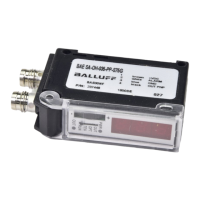
Fig. 2: Electrical connection and process connection
Adapter for process
connection
Torque Connection
per
EN 3852
Connection
per
EN 837
NPT
connection
1/4" approx. 5 Nm approx. 20 Nm
approx. 30 Nm
1/2" approx. 10 Nm approx. 50 Nm approx. 70 Nm
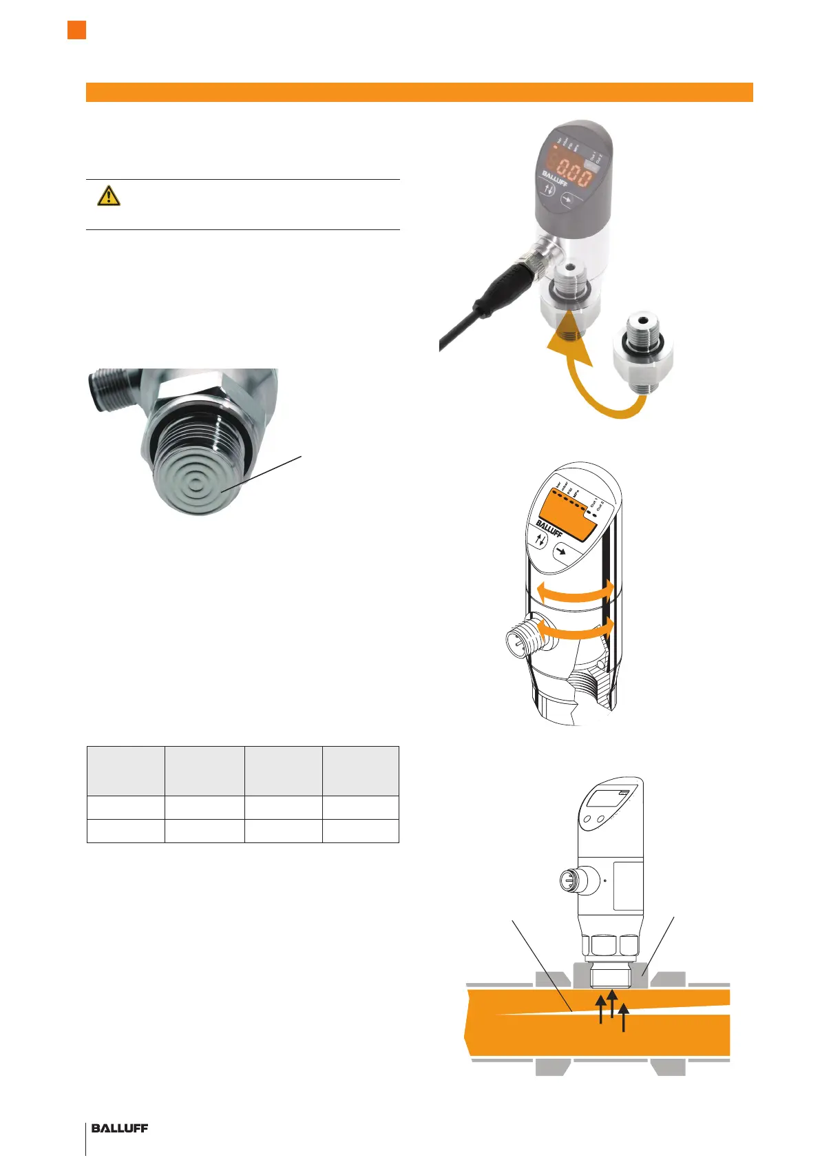
Fig. 3: Display and connection housing rotate 320°
Fig. 4: Process connection for the flush-mounted sensor (G1/2" in
accordance with EN 3852)
Factory-set
connection G1/2"
Fluid
Flush-mounted
sensor
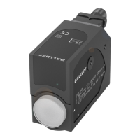
Important notes for installation of flush-mounted
sensors:
Caution!
Handle the unprotected membrane with the
utmost care: it can be easily damaged.
– Do not remove the packaging and protective cap until
shortly before installation, so that the membrane
remains undamaged. Retain the protective cap.
– After disassembly, place the protective cap back over
the membranes immediately.
– Do not use force when installing the sensor, so as not
to cause damage to the device or the system.
Membranes
Fig. 1: Unprotected membrane of the flush-mounted sensor
Pressure Sensors with IO-Link
BSP-B... /-V...
 Loading...