www.balluff.com 5English
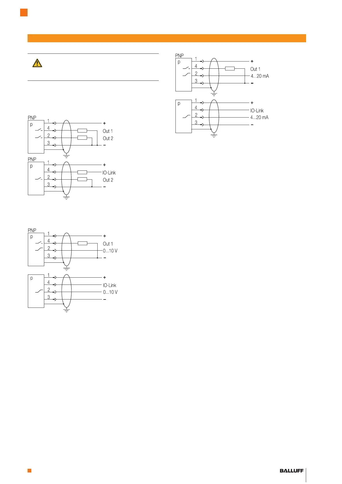
Establish the electrical connection to the device according
to the specifications indicated on the type plate and the
wiring diagrams below.
Caution!
Always depressurize and disconnect pressure
sensors from the power supply before establish-
ing an electrical connection.
Fig. 9: Sensor circuit diagram with analog output current
Electrical installation
Connector housing
Fig. 8: Sensor circuit diagram with 2 switching outputs
Connector housing
Standard IO Mode
IO-Link communica-
tion mode
Standard IO Mode
IO-Link communica-
tion mode
Fig. 10: Sensor circuit diagram with analog amperage output
Connector housing
Standard IO Mode
IO-Link communica-
tion mode
Pressure Sensors with IO-Link
BSP-B... /-V...
 Loading...