Preliminary Information
Banner Engineering Corp • Minneapolis, MN USA www.bannerengineering.com • Tel: 763.544.3164
Sensonix Incorporated • Plymouth, MN USA
9 of 18 www.sensonix.com • 763.519.7042
3.3 Set-up / Configuration
The gateway and nodes must be configured to create a communications link. A properly running
wireless network will be indicated on each endpoint node by LED1 flashing green every second. (The
gateway LED’s monitor the Modbus host link)
Complete the following configuration steps to set up the wireless link.
DC power or Battery power applied to all devices and powered up. (out of sleep mode) (See 4.2 Power
on / Power off)
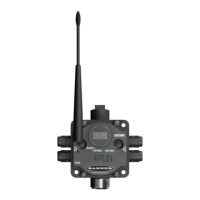
Gateway Set-up –
• Rotary switches = ‘00’
• Network ID set to a common value for the entire wireless network. The factory default is ‘01’
and will work for most single network installations. (See Setting the Network ID to change
the network ID)
• The Modbus slave number must be set to a unique number compared to other slaves on the
serial host bus. This is only required if using a host interface with the gateway.
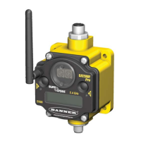
Node / Endpoint Set-up –
• Rotary switches = unique number for each node in the wireless network. 01-99, 00 is not valid
• LED1 will blink GREEN every second when a RF communications link is established.
• LED1 will blink RED every 3 seconds when a node is not communicating with the gateway.
*Some endpoint nodes may require up to 20 seconds after power-on to synchronize with the gateway.
3.4 LabView Configuration
Node configuration, Sensor configuration,
System Parameters – dynamic TDMA