Instruction Manual
Original Instructions
• Monitors emergency stop devices, such as palm buttons and rope/cable pulls,
and positive-opening safety switches used for guard/gate interlocking
• The safety inputs can monitor:
◦ A +24 V dc source switched by hard/relay contacts in single-channel
hookup, or
◦ Hard/relay contacts in a dual-channel hookup using terminals S11-
S12 and S21-S22
• The ES-FA-9AA has three normally open output switching channels for
connection to control-reliable power interrupt circuits
• The ES-FA-11AA has two normally open output switching channels for
connection to control-reliable power interrupt circuits and one normally
closed auxiliary output channel
• Automatic reset or monitored manual reset
• Design complies with standards ANSI B11.19, UL991, ISO 13850 (EN418),
and ISO 13849-1 (EN954-1) (Safety Category 4)
• For use in functional stop category 0 applications per ANSI NFPA 79 and IEC/
EN60204-1
• 6 or 7 amp safety output contacts, depending on model
• Plug-in terminal blocks
• 24 V ac/dc operation
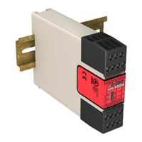
Models
Models
Supply Voltage Outputs Output Contact Rating
ES-FA-9AA
24 V ac/dc
3 Normally Open (NO) 6 A
ES-FA-11AA 2 Normally Open and 1 Normally Closed (NC) 7 A
WARNING: Not a Stand-Alone Safeguarding Device
This Banner device is not a stand-alone point-of-operation guarding device, as defined by
OSHA regulations. It is necessary to install point-of-operation guarding devices, such as safety light
screens and/or hard guards, to protect personnel from hazardous machinery. Failure to install point-
of-operation guards on hazardous machinery can result in a dangerous condition which could
lead to serious injury or death.
Important: Read this First
The user is responsible for satisfying all local, state, and national laws, rules, codes, and regulations relating to
the use of this product and its application. Banner Engineering Corp. has made every effort to provide complete
application, installation, operation, and maintenance instructions. Please contact a Banner Applications Engineer with any
questions regarding this product.
The user is responsible for making sure that all machine operators, maintenance personnel, electricians, and
supervisors are thoroughly familiar with and understand all instructions regarding the installation, maintenance, and use of
this product, and with the machinery it controls. The user and any personnel involved with the installation and use of this
product must be thoroughly familiar with all applicable standards, some of which are listed within the specifications.
Banner Engineering Corp. makes no claim regarding a specific recommendation of any organization, the accuracy or
effectiveness of any information provided, or the appropriateness of the provided information for a specific application.
Applicable U.S. Standards
ANSI B11 Standards for Machine Tools Safety
Contact: Safety Director, AMT – The Association for Manufacturing Technology, 7901 Westpark Drive, McLean, VA 22102,
Tel.: 703-893-2900
ES-FA-9AA and ES-FA-11AA E-Stop Safety
Module
Original Document
60606 Rev. G
12 August 2016