Overview
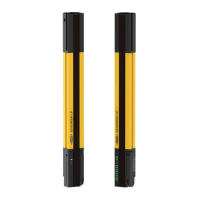
EZ-SCREEN LP
Instruction Manual
Components and Specifications
End-Cap Brackets
(model LPA-MBK-11*)
Side-Mount Bracket
(model LPA-MBK-12)
Figure 2-5. Included mounting bracket dimensions (for emitter or receiver)
2.7.3 Receiver Specifications, continued
Output Signal Switching Devices
(OSSDs)
Two redundant solid-state 24V dc, 0.5 A max. sourcing OSSD (Output Signal Switching Device) safety
outputs. (Use optional interface modules for ac or larger dc loads.)
Capable of the Banner “Safety Handshake” (see Section 1.1).
ON-State voltage: in-
OFF-State voltage: 1.2V dc max. (0-1.2V dc)
Max. load capacitance:0
Max. load inductance: 10 H
Leakage Current: 0.50 mA maximum
Cable Resistance:0 maimm
OSSD test pulse width: 100 to 300 microseconds
OSSD test pulse period: 10 ms to 22 ms (varies with number of beams)
Switching Current: 0-0.5 A
Auxiliary Output Switching
Capacity (OSSD/Fault)
Current-sourcing (PNP) solid-state output, 24V dc at 250 mA max. (see Section 3.5.5)
Controls and Adjustments
(see Section 4.2)
Scan Code selection: 2-position switch (code 1 or 2). Factory default position is code 1.
Trip/Latch Output selection: Redundant switches. Factory default position is T (trip).
EDM/MPCE monitor selection: 2-position switch selects between 1- or 2-channel monitoring. Factory
default position is 2-channel monitoring.
Reduced Resolution: Redundant switches. Factory default position is OFF.
Aux./Fault: 2-position switch. Factory default position is Aux.
Invert Display: 2-position switch. Factory default position is OFF.
Ambient Light Immunity
> 10,000 lux at 5° angle of incidence
Strobe Light Immunity
Totally immune to one Federal Signal Corp. “Fireball” model FB2PST strobe
Status Indicators
Yellow Reset indicator – indicates whether system is ready for operation or requires a reset
Bi-color (Red/Green) Status indicator – indicates general system and output status
Bi-color (Red/Green) Zone Status indicators – indicate condition (clear or blocked beam) of a
defined group of beams
7-Segment Diagnostic indicator (1 digit) – indicates proper operation, scan code, error code, or
total number of blocked beams
See Figure 1-3 for indicator locations and Section 4.4 for indicator conditions.
*Dimensions are in millimeters unless otherwise indicated. See Appendix A for more information.
32.0 [1.26"]
19.0 [0.75"]
39.8 [1.57"]
32.9 [1.30"]
16.0 [0.63"]
C
L
2x 10.0 [0.39"]
3x 5.5 [0.22"]
11.9 [0.47"]
10.0 [0.39"]
38.9 [1.53"]
29.0 [1.14"]
32.5 [1.28"]
9.5 [0.37"]
10.0 [0.39"]
6.0 [0.23"]
3x 5.5 [0.22"]
20.0 [0.79"]
10.0 [0.79"]
Buy: www.ValinOnline.com | Phone 844-385-3099 | Email: CustomerService@valin.com
 Loading...