Figure 7. Orientation for a height difference
Figure 8. Orientation for a color or luster
difference
Sensor Mounting
1. If a bracket is needed, mount the sensor onto the bracket.
2. Mount the sensor (or the sensor and the bracket) to the machine or equipment at the desired location. Do not
tighten at this time.
3. Check the sensor alignment.
4. Tighten the screws to secure the sensor (or the sensor and the bracket) in the aligned position.
Wiring Diagrams
shield
+
12-30V dc
D_Out
A_Out
Input
–
Load
* User-configurable PNP/NPN setting
4-20 mA
3
1
2
4
5
NPN
or
PNP
Figure 9. Analog Current Model
shield
+
12-30V dc
D_Out
A_Out
Input
–
Load
* User-configurable PNP/NPN setting
3
1
2
4
5
NPN
or
PNP
0-10V
Figure 10. Analog Voltage Model
Key
1 = Brown
2 = White
3 = Blue
4 = Black
5 = Gray
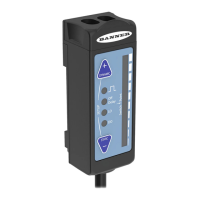
Display
Figure 11. LE550 Display in Run Mode
The display is a 2-line, 8-character LCD. The main screen is
the Run mode screen, which shows the real-time distance
measurement and the analog output measurement.
Buttons
Use the sensor buttons Down, Up, Enter, and Escape to program the sensor and to access sensor information.
L-GAGE
®
LE250/550 Analog-Discrete Laser Sensors
P/N 175093 Rev. E www.bannerengineering.com - Tel: +1-763-544-3164 3
 Loading...