Do you have a question about the Banner R-GAGE T30R and is the answer not in the manual?
Lists various sensor models with their specifications like beam pattern, range, connection, and output types.
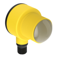
Explains the T30R's function as an industrial radar sensor using radio waves to detect various materials.
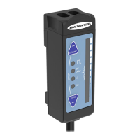
Details the sensor's LEDs (Power, Signal Strength, Output 1, Output 2, NO/NC) and their meanings.
Provides guidance on minimizing the tilt angle of a target relative to the sensor for proper sensing.
Step-by-step guide for mounting the sensor using its threaded barrel and lock washer.
Illustrates the connection setup involving the sensor, splitter, power supply, and PC.
Presents wiring diagrams for push-pull output, analog current, analog voltage, and dual discrete outputs.
Outlines the steps to download, install, and confirm the Banner Radar Configuration software.
Guides users to connect the sensor to the splitter cable, power, and PC, then connect via the software.
Provides an overview of the Banner Radar Configuration Software interface and its components.
Explains the options in the File, Sensor, and Help menus of the navigation toolbar.
Describes the data display area, legend for data selection, and axis adjustment controls.
Explains what the Summary pane displays: distance, signal strength, and output status.
Introduces the Sensor Settings pane for reading and writing sensor parameters.
Details parameters in the General tab: Response Speed, Target Selection, and Sensor Polarity.
Describes parameters on the Analog tab: Analog Span, Loss-of-Signal, and Averaging.
Explains parameters for Discrete 1 output: Output Mode, Distance Settings, and Output Settings.
Details parameters for Discrete 2 output: Output Mode, Distance Settings, and Output Settings.
Describes Pulse Pro/PFM settings for generating pulses proportional to sensor distance.
Explains controls for stopping, restarting, and recording live sensor data sampling.
Guides on using the Banner Radar Configuration software and PRO-KIT for sensor setup.
Details the IO-Link interface for sensor parameterization and data transmission.
Explains how to use push buttons for teaching the first and second points for configuration.
Explains using the remote input wire for programming the sensor remotely.
Details the procedure for teaching the first and second switch points using the remote input.
Explains using Remote Setup to configure output mode, analog slope, and teach modes.
Illustrates the remote input pulse sequences for various programming functions.
Provides detailed results and procedures for remote teach operations.
Explains analog and discrete teach modes within the remote setup.
Guides users on how to set the signal strength threshold using Sensitivity Selection.
Explains how to set the sensor's response speed using Speed Selection.
Describes how to set the target mode (Nearest/Strongest Target) using Target Selection.
Explains the two methods to reset the sensor to its factory default settings.
Lists the factory default settings for General, Analog, and Discrete tabs.
Illustrates Measurement Hold functionality with a distance vs. time graph and explanations.
Details sensor range, operating principle, frequency, linearity, repeatability, and environmental rating.
Covers supply voltage, power consumption, output configurations, protection, and max output power.
Describes response time, remote input, indicators, construction, temperature effects, and operating temp.
Details output ratings for analog current, analog voltage, and discrete outputs.
Lists output specifications for black wire configurations (IO-Link, PNP, NPN).
Lists output specifications for white wire configurations (PNP, NPN).
Details compliance with FCC Part 15 and Industry Canada regulations.
Lists operating system, hard drive space, and USB port requirements for the software.
Provides detailed dimensions for T30R-1515 models in integral and 150 mm QD configurations.
Provides detailed dimensions for T30R-4545 models in integral and 150 mm QD configurations.
Shows typical beam patterns in meters and degrees for T30R-1515 models with different targets.
Shows typical beam patterns in meters for T30R-4545 models with different targets.
Displays beam patterns in degrees for T30R-4545 models with varying signal strength thresholds.
Shows beam patterns in meters for T30R-4545 models with fixed target and signal strength thresholds.
Details the procedure for updating the Banner Radar Configuration Software using the installer.
Lists and describes various mounting brackets with their specifications.
Lists 5-pin M12 cordsets with shield, including lengths, styles, and pinouts.
Lists double-ended M12 cordsets with their lengths, styles, and pinouts.
Describes M12 splitter cordsets, their trunk/branch specs, and pinouts.
Lists the components included in the PRO-KIT configuration tool.
Advises against repairs and to contact Banner Engineering for troubleshooting and RMA.
Provides the headquarters address and phone number for Banner Engineering Corp.
Outlines copyright, license, and warranty disclaimers for the Banner software.
Details the limited warranty for Banner Engineering products, including exclusions.
| Brand | Banner |
|---|---|
| Model | R-GAGE T30R |
| Category | Accessories |
| Language | English |