EasyManua.ls Logo

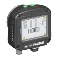
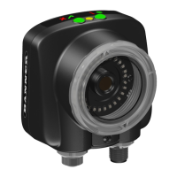
Banner iVu Series User Manual

Banner iVu Series
66 pages
To Next Page IconTo Next Page
Page #1 background imageLoading...
Page #1 background image
iVu Series Image Sensor
Rev. E 1/26/2012
143372

Table of Contents

Questions and Answers:

Banner iVu Series Specifications

General IconGeneral
Accessory TypeVision Sensor
Sensor TypeCMOS
Resolution640 x 480 pixels
Light SourceIntegrated LED
Communication InterfaceRS-232
Ingress ProtectionIP67
Operating Temperature0°C to 50°C (32°F to 122°F)

Summary

1 Product Support and Maintenance

1.1 Product Support

Provides resources for sensor setup and operation, including documentation and warranty service.

1.2 Maintenance

2 Overview of the Sensor

2.1 Typical iVu Applications

Lists common industrial applications where the iVu Series sensor is utilized for quality control.

2.2 Installing the Sensor

2.2.1 Installing and Connecting the Sensor

Details the process of mounting the iVu TG sensor using available brackets and connecting it.

2.2.2 Cable Connections for iVu TG with Integrated Display

2.2.3 Cable Connections for the iVu TG with a Remote Display

2.2.4 iVu Trigger, Remote Teach, and I/O Waveforms

2.3 Major Features

2.3.1 Demo Mode

Explains Demo Mode, which uses stored images to demonstrate sensor setup and adjustments.

2.3.2 Sensor Types

Area Sensor

Describes the Area sensor for detecting presence of features or holes on a part.

Blemish Sensor

Details the Blemish sensor for finding flaws or ensuring features exist under variable conditions.

Match Sensor

Explains the Match sensor for verifying patterns, shapes, or orientations against a reference.

2.3.3 Trigger Modes

3 Main Menu Reference

3.1 Main Menu Icons

Identifies and explains the function of key icons within the Main Menu.

3.2 System Menu

Describes the System menu for managing sensor settings, firmware, and configuration.

3.2.1 Sensor Type

3.2.2 Sensor Configuration

3.2.3 Sensor Information

3.2.4 Lock Sensor

3.2.5 Motion

3.2.6 Discrete I/O

Input Polarity

Output 1

Output 2

3.2.7 Display Settings

Advanced

3.2.8 Reboot Sensor

3.2.9 Firmware Update

3.3 Imager Menu

3.3.1 Auto Exposure

Optimizes exposure time and gain for current inspections.

3.3.2 Exposure

Controls the sensor's light sensitivity by adjusting exposure time.

3.3.3 Gain

Adjusts image brightness electronically without changing exposure time.

3.3.4 Trigger

3.3.5 Focus

3.3.6 Strobe

External

Configures the operation of an external light source.

Internal

Configures the operation of the integrated ring light.

3.3.7 FOV

Maximize FOV

Restores the Field of View (FOV) to its default, entire sensor display.

Modify FOV

Allows reducing the Field of View (FOV) to speed up processing or reduce noise.

3.4 Inspection Menu

3.4.1 Match

Sets parameters for Match inspection: ROI Type, Percent Match, Rotation Range, Pass Count.

ROI Type (Match)

Percent Match

Rotation Range

Pass Count (Match)

3.4.2 Area

ROI Type (Area)

Intensity Range

Area Range

Pass Count (Area)

3.4.3 Blemish

ROI Type (Blemish)

Sensitivity

Edge Length Range

Pass Count (Blemish)

3.4.4 Motion Parameters (Optionally Available for Area and Blemish)

Number of Edges

Sensitivity

Rotation

3.5 Logs Menu

3.5.1 Inspection Logs

Covers configuring and viewing logs of captured images, parameters, and results.

View Logs

Setup

3.5.2 System Logs

4 Setting up for an Inspection

4.1 Selecting a Sensor Type

Guides on choosing the appropriate sensor type (Match, Area, Blemish) for an inspection.

4.2 Acquiring a Good Image

Details capturing a clear image by checking lighting, angle, and using Auto Exposure.

Gain

Exposure

Focus

4.3 Configuring an Area Sensor

ROI

Intensity Range

Area Range

Pass Count (Area)

4.4 Configuring a Blemish Sensor

Sensitivity

Edge Length Range

Pass Count (Blemish)

4.5 Configuring a Match Sensor

ROI

Teach

Percent Match

Rotation Range

Pass Count

4.5.1 Remote Teach

5 Debugging Inspections

5.1 How to Round-Trip Debug Using the Emulator

Explains using the iVu Emulator for debugging inspections and parameter modification.

5.1.1 How to Debug Using the Emulator from a PC

Details the process of debugging inspections using the iVu Emulator on a PC.

5.1.2 How to Debug Using the Emulator from the USB Flash Drive

6 iVu Series: Updating the Sensor

6.1 Update Process

Provides steps for downloading and installing new iVu sensor firmware.

6.2 How to Set or Modify a Sensor Name

Explains how to assign or change the name of the iVu sensor.

6.3 How to Reset the Sensor Password

6.4 How to Use Bitmap Image Files with the iVu Emulator

7 LED Indicator Troubleshooting

7.1 Errors

Describes error indicators on the iVu sensor and how to resolve them.

7.2 Warnings

Explains warning conditions detected by the sensor and their interpretation.

8 Sensor Specifications

8.1 Models

Lists available iVu sensor models based on ring light and lens options.

8.2 Dimensions

C-Mount Lens Dimensions

Related product manuals