Power I/O Connections
Pin # Wire Color Description Direction
2 Brown 10-30V dc Input
7 Blue Common (Signal Ground) Input
6 Pink External Trigger Input
5 Gray Remote Teach Input
1 White Output 1 Output
8 Red Ready Output
4 Yellow Strobe Out (5V dc only) Output
3 Green Output 2 Output
9 Orange Not used N/A
10 Light Blue Not used N/A
11 Black Not used N/A
12 Violet Not used N/A
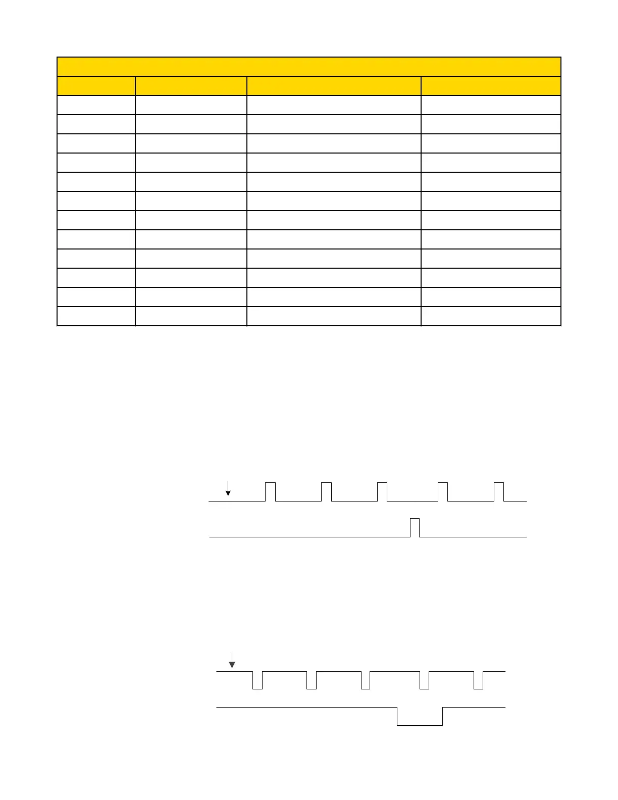
2.2.4 iVu Trigger, Remote Teach, and I/O Waveforms
The iVu has two input signals—Trigger and Remote Teach. The default setting is to detect the Trigger or Remote Teach input on the low
to high transition. This setting can be changed in the Main Menu > System > Discrete I/O > Input Polarity screen on the sensor.
iVu Low-to-High Trigger and Remote Teach Input Waveforms
The iVu Trigger and Remote Teach input waveforms are shown below.
Power up
Trigger
Remote
Teach
Pink
Wire Color
Function
Gray
The sensor triggers from low to high, and Remote Teach behaves electrically like trigger (see above).
iVu High-to-Low Trigger and Remote Teach Input Waveforms
The iVu High-to-Low Trigger and Remote Teach input waveforms are shown below.
Trigger
Remote
Teach
Pink
Wire Color
Function
Gray
Power up
iVu Series Image Sensor
12 www.bannerengineering.com - tel: 763-544-3164 Rev. E

 Loading...