B
Power I/O Connections
Pin # Wire Color Description Direction
2 Brown 10-30V dc Input
7 Blue Common (Signal Ground) Input
6 Pink External Trigger Input
5 Gray Remote Teach Input
1 White Output 1 Output
8 Red Ready Output
4 Yellow Strobe Out (5V dc only) Output
3 Green Output 2 Output
9 Orange Not used N/A
10 Light Blue Not used N/A
11 Black Not used N/A
12 Violet Not used N/A
NOTE: Microlens model shown, C-Mount model connections are identical.
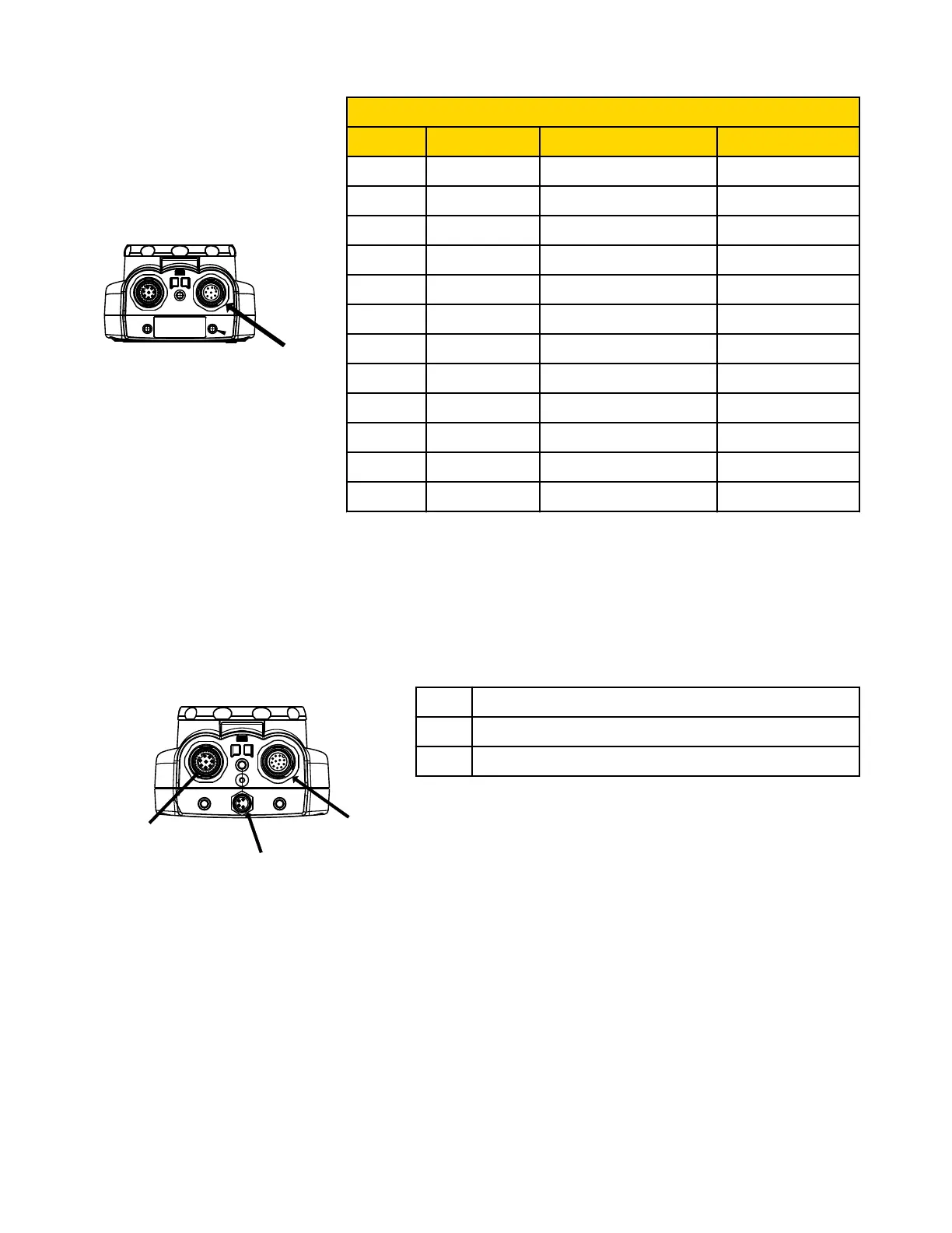
2.2.3 Cable Connections for the iVu TG with a Remote Display
The cable connections on the iVu sensor are shown below, and power I/O connections (B) are defined in the Power I/O Connections
table below.
B
A
C
A Remote Display Connector
B Power I/O Connector
C USB Connector
NOTE: Microlens model shown, C-Mount model con-
nections are identical.
iVu Series Image Sensor
Rev. E www.bannerengineering.com - tel: 763-544-3164 11

 Loading...