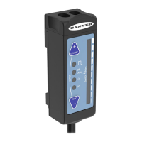
2.3 Connect to the Sensor
A = Pro Converter Cable (MQDC-506-USB)
B = Splitter (CSB-M1251FM1251M)
C = PC running Banner Radar Configuration software
D = T30R
E = Power Supply (PSW-24-1 or PSD-24-4)
F = Optional 5-Pin to 5-Pin Double-Ended Cordset (ex.
MQDEC3-515SS)
2.4 Wiring
Quick disconnect wiring diagrams are functionally identical.
Push-pull Output and Analog Current Output
+
10–30 V dc
D_Out/IO-Link
A_Out
Input
–
Load
* Push-Pull output. User-configurable PNP/NPN setting.
4-20 mA
bu
bn
wh
bk
gy
*
*
PNP
NPN
Push-pull Output and Analog Voltage Output
+
12–30 V dc
D_Out/IO-Link
A_Out
Input
–
Load
* Push-Pull output. User-configurable PNP/NPN setting.
0-10 V
bu
bn
wh
bk
gy
*
*
PNP
NPN
Dual Discrete Output
+
10–30 V dc
D1_Out/IO-Link
D2_Out
Input
–
* Push-Pull output. User-configurable PNP/NPN setting.
bu
bn
wh
bk
gy
PNP
NPN
or
Load
Load
Key:
1 = Brown
2 = White
3 = Blue
4 = Black
5 = Gray (Connect for use with remote input or
Banner Radar Configuration software)
2.5 Install the Software
Important:
Administrative rights are required to install the Banner Radar Configuration software.
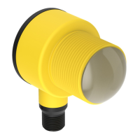
R-GAGE
®
T30R Sensor
6 www.bannerengineering.com - Tel: + 1 888 373 6767
 Loading...