Model
1
Glass Fiber Optic Mode Range Output
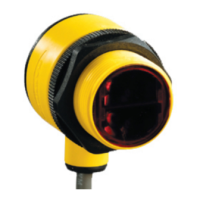
QS18VN6F 940 nm Infrared
Range varies by sensing mode
and fiber optics used
NPN
QS18VP6F PNP
Wiring Diagrams
QS18 with NPN Outputs
10–30 V dc
–
+
bn (1)
bu (3)
wh (2)
bk (4)
Load
Load
QS18 with PNP Outputs
10–30 V dc
–
+
bn (1)
bu (3)
wh (2)
bk (4)
Load
Load
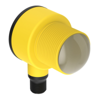
QS18 Emitters
4-pin M12/Euro-style Models (Male)
4-pin M8/Pico-style Models (Male)
Key
1 = Brown
2 = White
3 = Blue
4 = Black
Installing Fibers
Cutting Unterminated Plastic Fibers QS18V..6FP
Unterminated plastic fibers are designed to be cut by the user to the length required for the application.
To facilitate cutting, a Banner model PFC-1 cutting device is supplied with the
fiber. Cut the fiber as follows:
Cutting Ports
Lift to Open Ports
Figure 1. PFC-1 Cutting Device
Use small ports for fiber sizes:
• 0.25 mm (0.01 inches)
• 0.5 mm (0.02 inches)
Use large ports for fiber
sizes:
• 0.75 mm (0.03 inches)
• 1.0 mm (0.04 inches)
• 1.5 mm (0.06 inches)
1. Locate the control end of the
fiber
(the unfinished end).
2. Determine the length of fiber required for the application. If using a bifurcated fiber,
separate the two halves of the fiber at
least 51 mm (2 inches) beyond the fiber cutting location.
3. Lift the top (blade) of the cutter to open the cutting ports.
4. Insert one of the control ends through one of the cutting ports on the cutter so that the excess fiber protrudes from the
back of the cutter.
5.
Double-check the
fiber length, and close the cutter until the fiber
is cut.
6. Using a different cutting port, cut the second control end to the required length.
Note: To ensure a clean cut each time, do not use a cutting port more than once.
7. Gently wipe the cut ends of the fiber
with a clean, dry cloth to remove any contamination. Do not use solvents or abrasives
on any exposed optical fiber.
WORLD-BEAM
®
QS18 Series Sensor
P/N 197052 Rev. F www.bannerengineering.com - Tel: + 1 888 373 6767 3

 Loading...