1. Fan replacement kit
Image 1-8
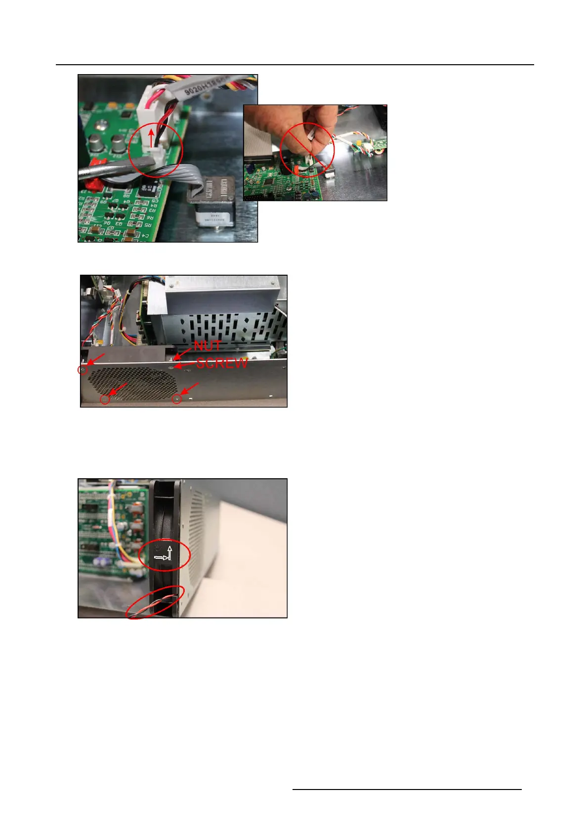
2. R emov e four 6–32 x 1/2” flat-head Phillips screws and four 6–32 Keps nuts holding the fan to the chassis.
Image 1-9
3. R emov e the fan assem bly.
4. Install the new fan assembly, using four 6–32 x 1/2” flat-head Phillips sc rews and four 6–32 Keps nuts.
Note: New screws and nuts for this are included in the kit, as e xisting hardware may be covered in old Loc tite.
Make sure that the w ires and arrows indicating air flow direction are in the correct orientation.
Image 1-10
5. C onnect the fan power cable to t
he front panel board socket CN1. The connector is keyed to go into th e socket in only one
direction.
R59770891 AP20 & AP24 FAN REPLACEMENT KIT 28/09/2015
5