1. Filter Assembly
1. FILTER ASSEMBLY
About
This chapter describes how to assemb le and install the filter
The filter kit is delivered as a complete kit, but not pre-assembled. The assembly of the kit is performed in par allel with the installation.
Due to a change in airflow when the filter is installed, the fan speed may increase and impact the perceived fan noise.
1.1 Kit Content
Kit Content
Article Number Description Pcs
400–0946 S/A Dust fi lter 1
505–0276 S/D filter sc rew 6
1.2 Environmental conditions
Due to changed airflow resistance w h en filter is installed, there are changes in the ambient operating conditions for the projector.
See table below.
Environment Ambient operating t emp erature Relative humidity
0 – 500m
+10 – 40°C 10 – 80% RH
500 – 3000m
+10 – 35°C 10 – 80% RH
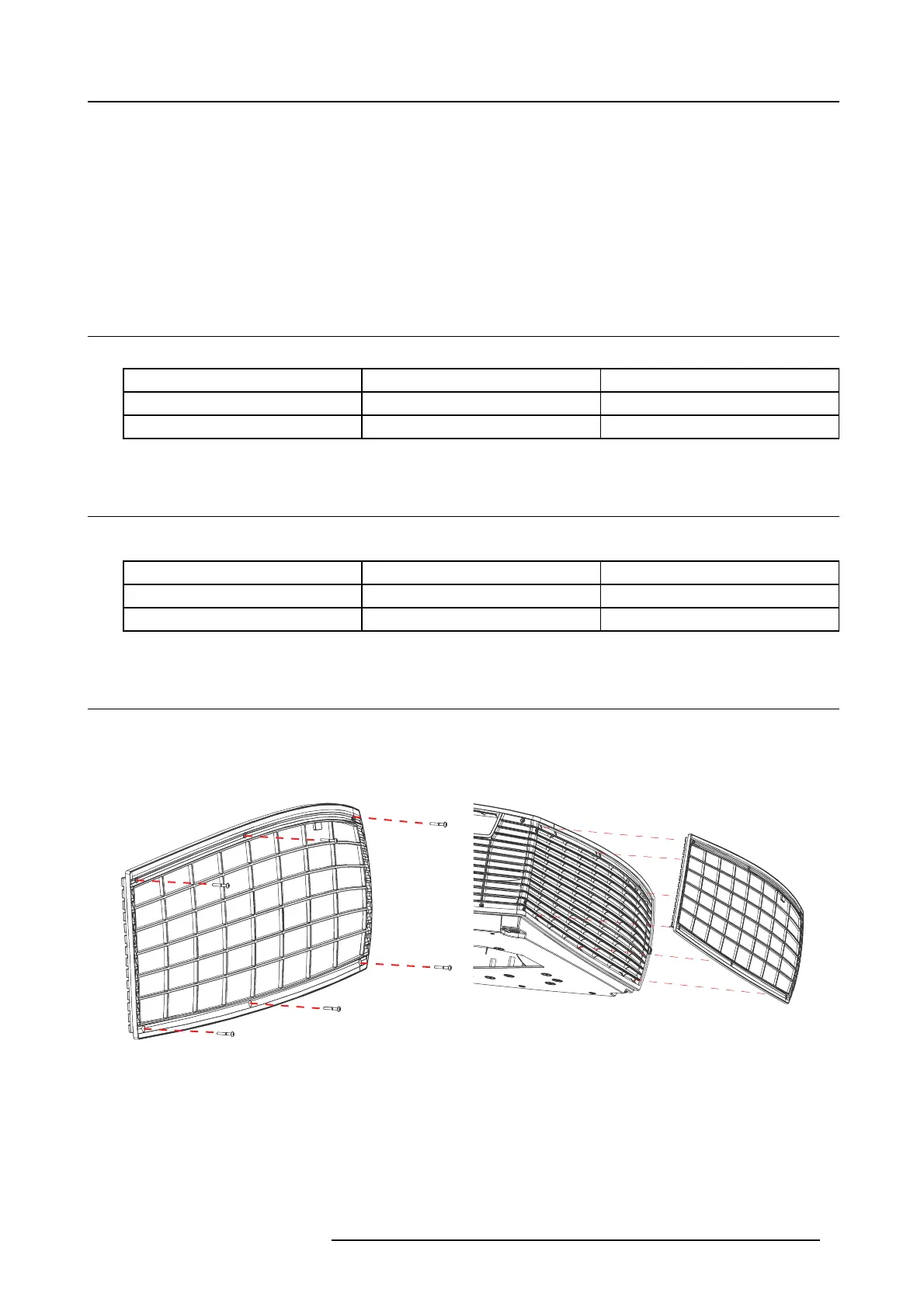
1.3 Assembly and installation
1. Put the screws (505–0276) in to the holes as indicated in the illustration below. Press the screw until it is snaps into position
2. Apply the filter frame over the projector’s side cover. E nsure that the captive screws in the filter frame align with the holes in the
projector side cover, as shown in the illustration.
Image 1 -1
Entering the captive screws
Image 1-2
Applying the filter frame
3. Ensure that the m icro switch at the top of the side cover is engaged by the stud on the filter frame.
601–0456 F90 DUST FILTER 14/08/2017
1

 Loading...


