Manual 2100-671
Page 33 of 44
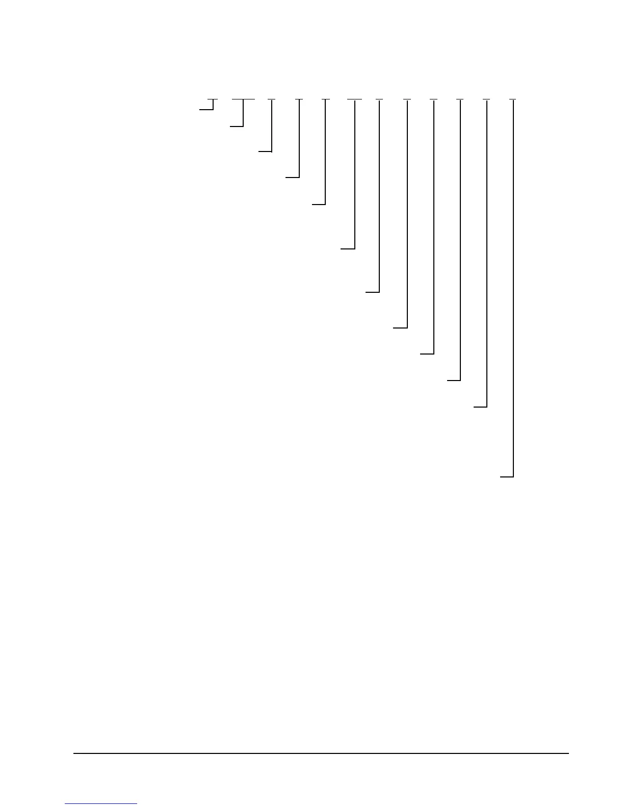
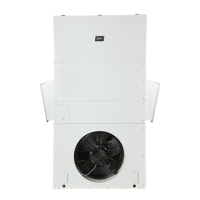
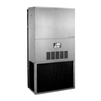
FIGURE 49
MEGA-TEC Wall-Mount Unit Model Nomenclature
CONTROL LOGIC AND CLIMATE OPTIONS
P – Programmable Logic Board
W 120 A P B 0Z E P 1 X X X
MODEL SERIES
REVISION
A – Revision Level
MAXIMUM SENSIBLE CAPACITY
120 – 10 Ton 3 Stage Capacity
VOLTS & PHASE
Q – 575-60-3
V – 415/380-50-3
ELECTRIC HEAT
0Z – O kW with Circuit Breaker
09 – 9 kW with Circuit Breaker
18 – 18 kW with Circuit Breaker
VENT PACKAGE
B – No Vent
E – Economizer (DB and WB)
FILTER
M – MERV11 Disposable P – MERV8 2" Pleated N – MERV13 2" Pleated
COLOR AND CABINET FINISH
1 – White Baked Enamel Finish
OUTLET
X – Future Use
COIL AND UNIT COATING OPTIONS
X – Copper/Aluminum Evaporator Coil, Copper/Aluminum Condenser Coil
1 – Coated Evaporator Coil
2 – Coated Condenser Coil
3 – Coated Evaporator Coil, Coated Condenser Coil
4 – Condenser Section Component Coating, Coated Evaporator Coil, Coated Condenser Coil
5 – Internal and External Cabinet Component Coating, Coated Evaporator Coil, Coated Condenser Coil
ACCESSORIES AND CONTROLS OPTIONS
X – Standard accessories including airflow sensor, dirty filter sensor, pressure transducers, crankcase heater
B – 230/208-60-3
C – 460-60-3
E – 220/200-50-3