Manual 2110-1418G
Page 15 of 16
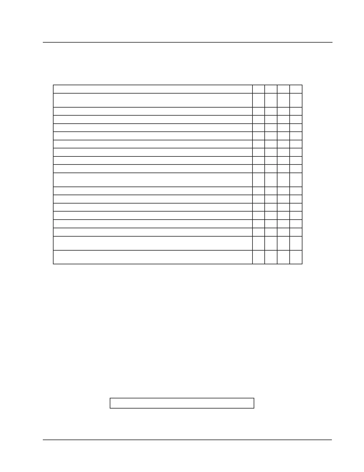
CONTROL PANEL – RIGHT & LEFT HAND
NS – Not Shown
Circuit breakers listed are for units without electric heat "0Z" models.
See Heater Replacement Parts Manual for units with electric heat.
This table references layout views on pages 13 & 14
W6RV2-S
W6RV2-T
W6LV2-S
W6LV2-T
Drawing No. Part No. Description
1 8607-036 Low Voltage Terminal Strip X X X X
4
4
8407-071
8407-072
Transformer
Transformer
X
X
X
X
5 8401-037 Compressor Contactor X X X X
7 135-130 Wire Shield X X X X
8 8611-006 Ground Terminal X X X X
9 3000-1463 6 Pin Connector X X X X
10 8201-148 Compressor Control Module X X X X
11 8201-126 Phase Monitor X X X X
14 8201-062 Alarm Relay X X X X
15 S117-350 Low Voltage Box X X X X
16
16
117X351
117Y351
Control Panel
Control Panel
X X
X X
18 8301-041 5VDC Supply X X X X
19 8201-149 Solid State Relay X X X X
NS 8301-014 Outdoor Air Sensor X X X X
NS 8403-066 Thermostat Controller X X X X
NS 8615-043
Circuit Breaker 40A 3 Pole (Opt)
X X
NS 8615-101 Toggle Disconnect (Optional) X X
NS
NS
3000-1361
3000-1230
Pressure Transducer Harness
Compressor Harness
X
X
X
X
X
X
X
X
NS
NS
4095-275
4095-375
Wiring Diagram
Wiring Diagram
X
X
X
X
 Loading...