26-3
®
GENERAL HVAC SYSTEM
This section outlines general service guidelines for a common HVAC system.
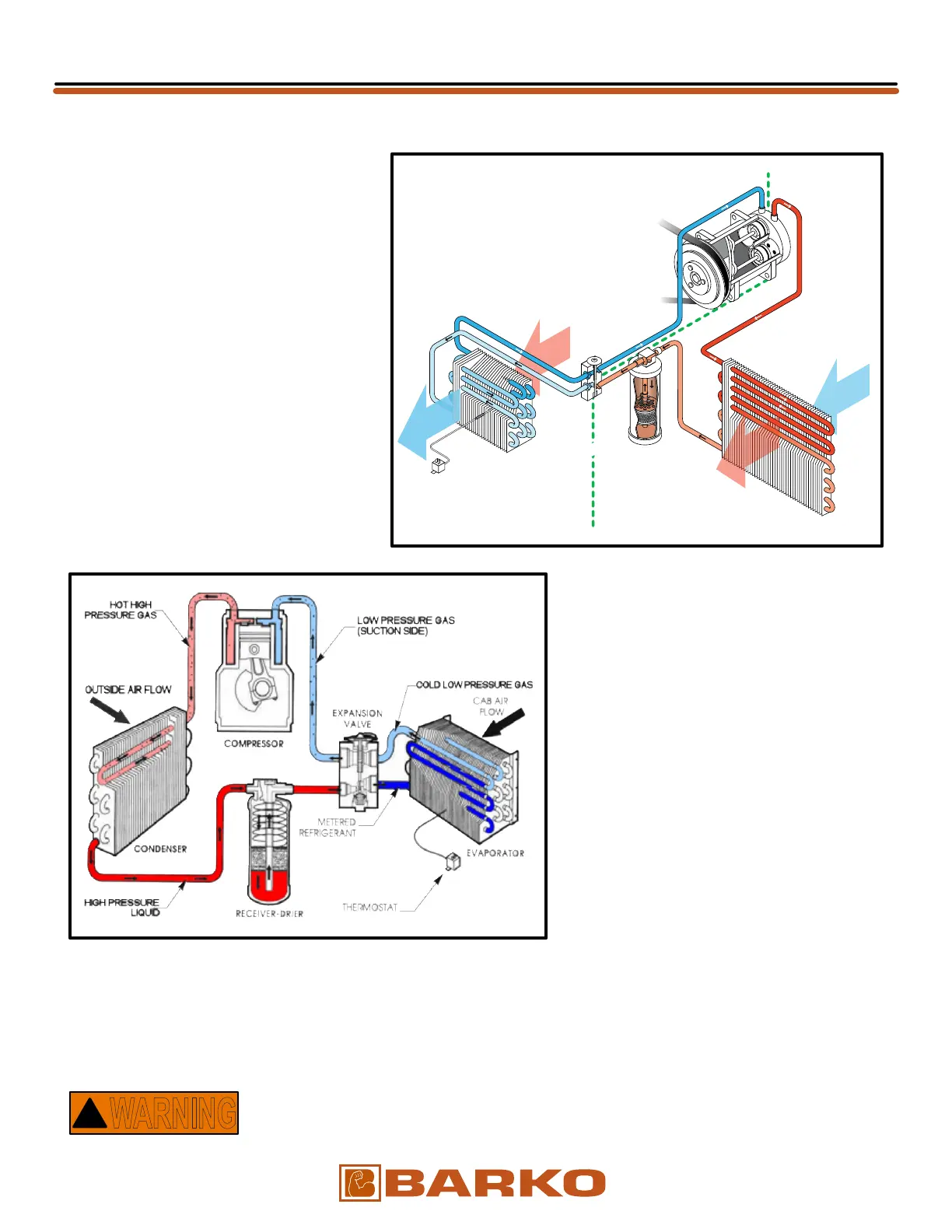
Figs 1 & 2 show the components and
flows of a typical A/C system. There
are two basic system configurations:
systems that use expansion valves and
systems that use orifice tubes. BARKO
machines use the expansion valve
system.
In the Expansion Valve System (see
Fig-1), the high side begins at the
compressor, continues through the
condenser, on through the receiver/drier
and ends at the expansion valve. The
low side begins where the high side left
off, at the expansion valve. From there it
continues through the evaporator and
ends at the compressor.
Air Conditioner components are shown
in Fig-2 connected together to illustrate
system operation. The components
shown are not to scale and may not be an
exact replication of your BARKO system.
The refrigerant and refrigerant oil are clear
in color and not visible in this drawing.
The small arrows inside the components
and connecting hoses show the direction
of refrigerant flow.
Allow only certified personnel to service and maintain the air conditioning system. The Clean Air Act
of 1992 states that anyone who works on air conditioning systems must be certified as proof of their
training. Organizations such as the Mobile Air Conditioning Society (MACS) and the National Institute for
Automotive Service Excellence (ASE) are approved by the Environmental Protection Agency (EPA) as
organizations with approved independent testing and certification programs. Contact your local EPA office
for more information.
Air conditioning systems operate under extreme high pressure. The
containers refrigerants are sold in are also under pressure.
1 AIR CONDITIONING (A/C) SYSTEM:
Fig-1
Fig-2
WARNING
!
LOW SIDE HIGH SIDE
WARM
INLET AIR
COOL
OUTSIDE
AIR FLOW
HEATED
OUTSIDE
AIR FLOW
COOL
AIR TO
THE CAB
Condenser
Expansion
Valve
Compressor
Receiver
Drier
Evaporator
Thermostat
#10 Hose
Low Pressure
Gaseous State
(Suction Side)
17-30 PSI
#6 Hose
Liquid
State
#8 Hose
Hot (200°) High Pressure
Gaseous State
#10 Hose
Cold Low Pressure
Gaseous State
300 PSI
#8 Hose
Metered
Refrigerant
Gaseous
State
#6 Hose
High Pressure
Liquid State
135°
06/03/2019
Updated
OPERATOR’S