3-2 BE1-50/51M - Functional Description
CAUTION
Trip circuit voltage is present at the front panel test points. When shorting the test points,
use insulated jumpers to avoid contact with these voltages.
POWER
CT SUPPLY
POWER
BRIDGE
CT
SIGNAL
TIME
SCALE
INST
SCALE
MUX
SW SW SW SW
TIME
PICKUP
INST
PICKUP
SWSW
SW
DOG
WATCH
SUPERVISOR
MICRO
51
50
TIME
DIAL
TIME
CURVE
50/60 Hz
INST DELAY
TP
TP
AUX
ISOLATION
TARGETS
MAGNETIC
ACTIVE/PICKUP
51
50
INPUT
GND
11-16-00
D1181-09
2
3
6
5
4
7
8
9
AND
A/D
CONVERTER
POWER-OFF
SENSING
SERIES 200 RELAYS ONLY
SW
RESET CHAR.
51
50
Power-Off Sensing
In 200 series relays, the power-off sensing circuits measure the decaying voltage to determine the length of time
that power is removed (zero current). This provides information for the integrating reset function even when
power has been entirely removed.
Outputs
Instantaneous And Timed
System circuit breakers controlled by the output contacts can be manually tripped by applying a short across the
TIME or INST MANUAL TRIP front panel test points. Targets will not be pulled for a manual trip if the relay is
de-energized. Current flow in the trip circuit is indicated by the operation of the target. The targets will not
operate without adequate operating power for the relay.
Auxiliary
The auxiliary output contacts can be configured by the user to close when the timed and/or instantaneous trip
occurs. With both jumpers installed (this is the factory setting) either the timed or instantaneous trip closes the
auxiliary contacts. Effective with unit revision R, in units 9 2520 00 100 through 109, the printed circuit board
was changed. Now, the PCB for 100 and 200 series relays are similar. User’s with units previous to revision
R may see Section 8,
Relay Differences
, for installing auxiliary output contact jumpers.
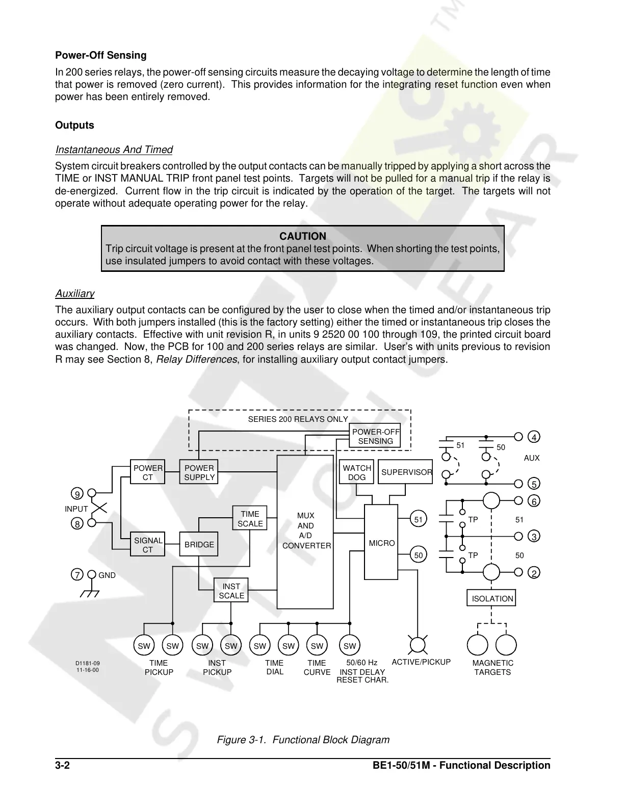
Figure 3-1. Functional Block Diagram
Courtesy of NationalSwitchgear.com
 Loading...


