BE1-50/51M - Installation 4-1
SECTION 4 • INSTALLATION
GENERAL
When not shipped as part of a control or switchgear panel, the relays are shipped in sturdy cartons to prevent
damage during transit. Immediately upon receipt of a relay, check the model and part number against the
requisition and packing list to see that they agree. Visually inspect the relay for damage that may have occurred
during shipment. If there is evidence of damage, immediately file a claim with the carrier and notify the Regional
Sales Office, or contact the Sales Representative at Basler Electric, Highland, Illinois.
Proper operation of the relay may be confirmed by performing the operational test procedure in Section 5. In
the event the relay is not to be installed immediately, store the relay in its original shipping carton in a moisture
and dust free environment.
DIELECTRIC TEST
In accordance with IEC 255-5 and IEEE C37.90-1989, one-minute dielectric (high potential) tests may be
performed as follows:
All circuits to ground: 2828 Vdc
Input to output circuits: 2000 Vac or 2828 Vdc
Output contacts are surge protected.
MOUNTING
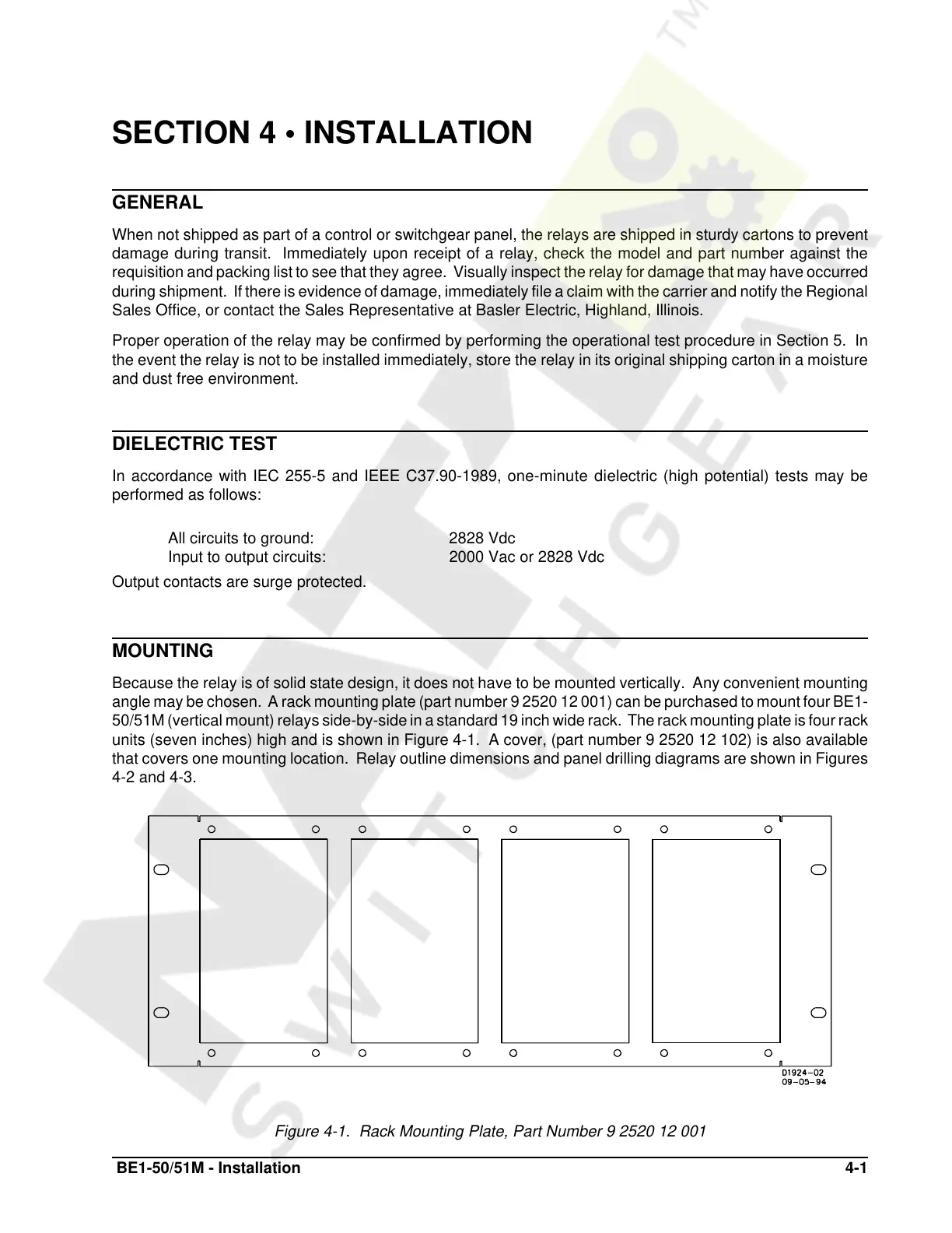
Because the relay is of solid state design, it does not have to be mounted vertically. Any convenient mounting
angle may be chosen. A rack mounting plate (part number 9 2520 12 001) can be purchased to mount four BE1-
50/51M (vertical mount) relays side-by-side in a standard 19 inch wide rack. The rack mounting plate is four rack
units (seven inches) high and is shown in Figure 4-1. A cover, (part number 9 2520 12 102) is also available
that covers one mounting location. Relay outline dimensions and panel drilling diagrams are shown in Figures
4-2 and 4-3.
Figure 4-1. Rack Mounting Plate, Part Number 9 2520 12 001
Courtesy of NationalSwitchgear.com
 Loading...


