10
HARDWARE INSTALLATION
2. If you are using an external power supply:
a. Plug one end of the CoaXPress cable into the Micro-BNC (HD-BNC)
connector of the camera and plug the other end of the CoaXPress
cable into the Micro-BNC port of the interface card.
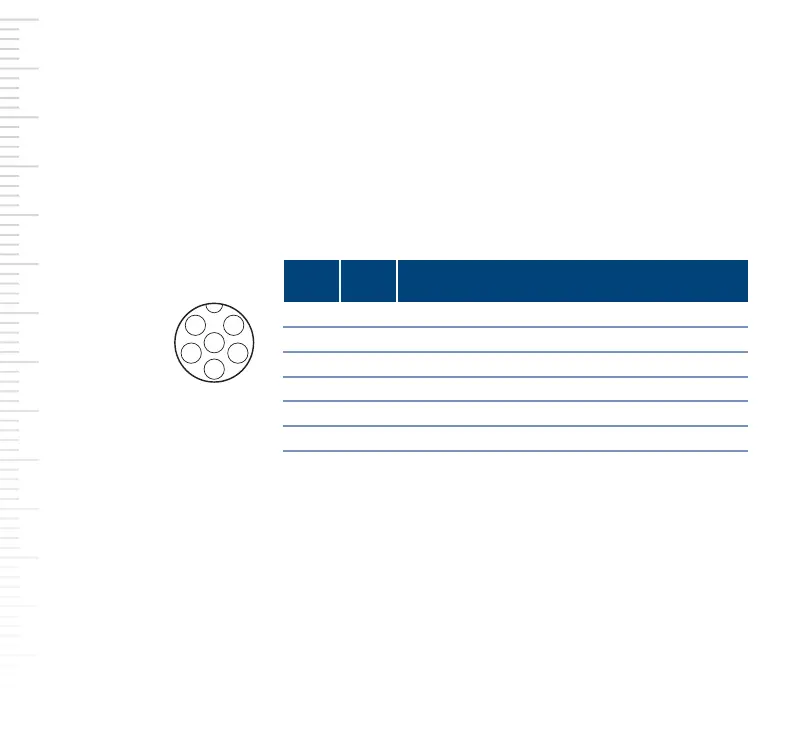
b. Connect the plug of the power I/O cable to the M8 6-pin connector
of the camera.
Observe the following pin assignment.
c. Connect the open end of the power I/O cable to a power supply.
d. Plug the power supply into a power outlet.
3. Reconnect the computer to the power outlet and boot the computer.
For information about the different LED states and corresponding colors,
refer to the Basler Product Documentation available at:
docs.baslerweb.com
Pin Line Function
I/O connector
of the camera
(M8 6-pin)
1 24 VDC camera power
2 1 Opto-coupled I/O input line
3 Ground for opto-coupled I/O lines
4 2 General purpose I/O (GPIO) line
5 3 General purpose I/O (GPIO) line
6 Ground for camera power and GPIO lines
4