9469200994 Rev — 9
DGC-2020ES Typical Connections
Typical Connections
Typical connection diagrams are provided in this chapter as a guide when wiring the DGC-2020ES for
communication, mechanical senders, contact inputs and outputs, sensing, and control power.
Connections for Typical Applications
Typical connections for applications using three-phase wye, three-phase delta, single-phase AB, and
single-phase AC generator voltage sensing are shown on the following pages.
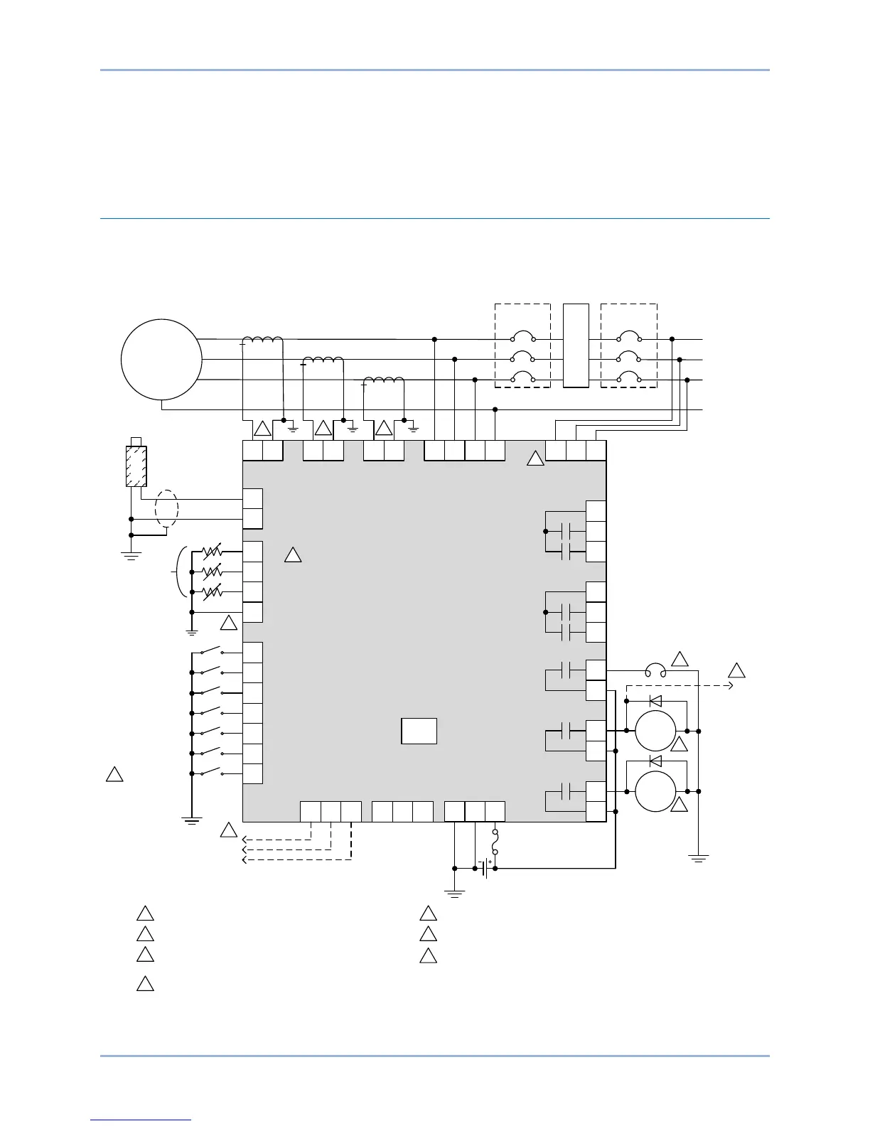
Figure 4 illustrates typical three-phase wye generator voltage sensing connections.
Figure 4. Three-Phase Wye Connections for Typical Applications
GENERATOR
≤ 480V
32
31
MPU+
MPU–
38
IA–
37
IA+
36
IB–
35
IB+
34
IC–
33
IC+
45
GEN VA
43
GEN VB
41
GEN VC
40
GEN VN
48
BUS VB
50
BUS VC
A
B
C
N
25
26
OUT 1
27
28
29
30
OUT 2
OUT 3
OUT 4
23
24
21
22
19
20
PRE
RUN
START
START
SOLENOID
FUEL
SOLENOID
17
BATT–
18
BATT+
16
CHASSIS
GLOW PLUGS
52
53
OIL
COOLANT
1
2
FUEL
SENDER COM
9
8
7
6
5
4
3
INPUT 7
INPUT 6
INPUT 5
INPUT 3
INPUT 4
INPUT 2
INPUT 1
P0071-48
M
P
U
GEN CKT
BKR
L1
L2
L3
N
Analog
Senders
12/24V
Mini-B
USB
11
RDP TxD +
12
485 SHIELD
10
RDP TxD –
14
CAN L
15
SHIELD
13
CAN H
1
1 1
2
DGC-2020ES
1
Labels indicate the functions assigned by the default programmable
logic to the contact inputs.
2
Current inputs are 1A or 5A, depending on style.
4
Connect near engine block (negative battery terminal) side of senders.
MAINS CKT
BKR
L
O
A
D
46
BUS VA
Emergency Stop
4
7
Bus sensing inputs are optional, depending on style.
7
To ECU
CAN bus
To ECU
Power or
Key-on
Terminal
6
5
If component is under ECU control, do not connect to DGC-2020ES.
Connect to the ECU on an electronically controlled engine when the
DGC-2020ES has the J1939 CAN interface option (style xCx).
6
6
5
5
5
Oil pressure and coolant temperature senders are only available when
the DGC-2020ES has the Analog Senders option (style xAx). The fuel
sender is always available.
3
3

 Loading...


