1-2 9469300994
Mounting DGC-2020HD
In Figure 1-1, the horizontal drilling measurement of 10.75 inches has a tolerance of +0.01/–0.01 inches.
The horizontal cutout measurement of 10.38 inches has a tolerance of +0.04/–0 inches. The vertical
drilling measurement of 7.25 inches has a tolerance of +0.01/–0.01 inches. The vertical cutout
measurement of 6.88 inches has a tolerance of +0.04/–0 inches.
DIN Rail Configuration
Units with style xRxxxxxxx are mounted on DIN rails. In this configuration, the DGC-2020HD has no HMI.
The rear of the DGC-2020HD faces outward for convenient access to terminals and connections.
Hardware
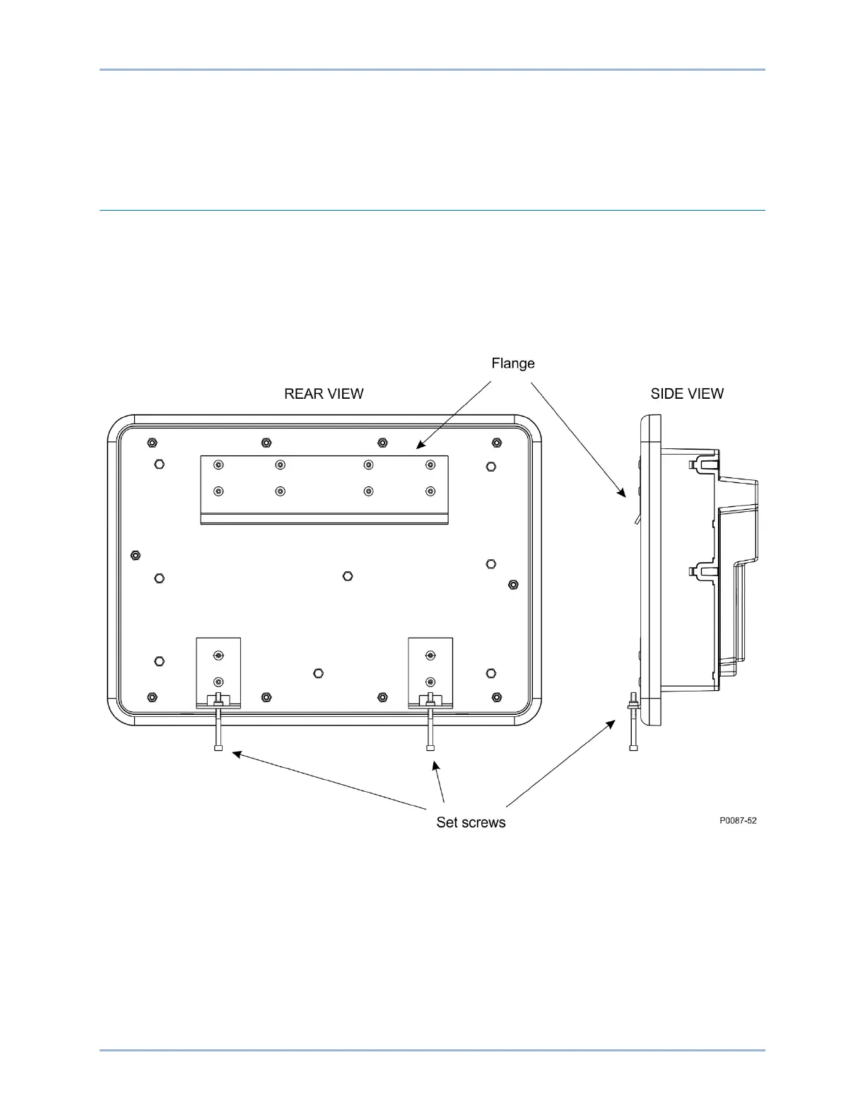
Two DIN rails, one located above the other, are required for mounting the DGC-2020HD. One flange and
two set screws on the DGC-2020HD secure it to the DIN rails. The flange clips onto the upper rail and the
set screws attach to the bottom rail. See Figure 1-2 for flange and set screw locations.
Figure 1-2. DIN Rail Flange and Setscrew Locations for Style xRxxxxxxx
Use two steel Top Hat rails, 35 mm x 7.5 mm, that are a minimum of 13 inches (330 mm) in length. DIN
Rail mounting hardware should be spaced no more than 6 inches (152 mm) apart for proper support.
Using the supplied hex key, hand tighten set screws until they stop. Locking inserts help maintain set
screw tightness. Hand tightening is recommended to ensure proper locking insert performance.
Dimensions
DIN Rail mounting dimensions are shown in Figure 1-3. All dimensions are shown in inches with
millimeters in parenthesis.