EasyManua.ls Logo

Bauer 20744E-B - User Manual

Bauer 20744E-B
17 pages
Print Icon
To Next Page IconTo Next Page
Loading...
!"#$%&'()*$&+"(*&+$,)-)#$(./
01+1#&"2-&3$4+1#$&)#%&5##,%66333/5)-4"-7-$185#/9":
;:)1(&"2-&#$95<19)(&+2,,"-#&)#%&,-"*29#+2,,"-#=5)-4"-7-$185#/9":
Owners Manual & Safety Instructions
Save This Manual Keep this manual for the safety warnings and precautions, assembly,
operating, inspection, maintenance and cleaning procedures. Write the product’s serial number in the
back of the manual near the assembly diagram (or month and year of purchase if product has no number).
Keep this manual and the receipt in a safe and dry place for future reference. 20i
When unpacking, make sure that the product is intact
and undamaged. If any parts are missing or broken,
please call 1-888-866-5797 as soon as possible.
Copyright
©
2020 by Harbor Freight Tools
®
. All rights reserved.
No portion of this manual or any artwork contained herein may be reproduced in
any shape or form without the express written consent of Harbor Freight Tools.
Diagrams within this manual may not be drawn proportionally. Due to continuing
improvements, actual product may differ slightly from the product described herein.
Tools required for assembly an d se rv ic e may n ot b e in cl uded.
Read this material before using this product.
Failure to do so can result in serious injury.
SAVE THIS MANUAL.
Question and Answer IconNeed help?

Do you have a question about the Bauer 20744E-B and is the answer not in the manual?

Overview

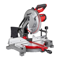
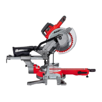
This document is an Owner's Manual & Safety Instructions for a Bauer 12" Compound Miter Saw, model 20744E-B, with item number 57608.

Function Description:

The Bauer 12" Compound Miter Saw is a power tool designed for cutting wood and wood-like products. It is specifically intended for making miter cuts (angles across the horizontal surface of the material) and bevel cuts (angles vertically), as well as compound angles (a combination of miter and bevel cuts). The saw is not to be used with abrasive cut-off wheels for cutting ferrous materials like bars, rods, or studs, as abrasive dust can jam moving parts and sparks can damage plastic components. The tool is designed for precision cutting in various applications, including crown moldings, picture frames, and other trim materials. It features adjustable miter and bevel angles, a workpiece clamp for secure material handling, and a dust collection system.

Important Technical Specifications:

  • Electrical Rating: 120VAC / 60Hz / 15A
  • Rated No Load Speed: 3800 RPM
  • Cutting Capacity at 45° L: 1-1/2" x 5-1/2"
  • Cutting Capacity at 90° L/R: 2-5/8" x 7-5/8"
  • Maximum Bevel: 48° Left – 3° Right
  • Maximum Miter: 48° Left and Right
  • Saw Blade: 12" Diameter, 1" Round Arbor, 4000 Minimum RPM Rating (Note: Blade sold separately)

Usage Features:

  • Mounting: The miter saw must be mounted to a stable and secure support (e.g., a bench) using its four bolt holes before use. Mounting hardware is not included.
  • Dust Collection: The saw includes a Dust Collection Bag that slides over the Dust Outlet at the rear of the Saw Head Assembly. Alternatively, a dust extraction device can be connected to the Dust Outlet for a more comprehensive dust collection system.
  • Saw Blade Selection: Only saw blades with a 12" diameter, 1" round arbor, and a speed rating equal to or higher than 4000 RPM should be used. The blade must be suitable for the material being cut.
  • Guard Setup: The Lower Blade Guard must be in place, move freely, and close instantly to ensure safety.
  • Adjusting Miter Angle: The Miter Lock Knob is loosened to unlock the Miter Table. The Miter Detent Lock Lever is pressed down to move the Table to the desired angle. Pre-set detents are available for common angles (0°, 15°, 22.5°, 30°, 31.6°, 45°, and 48° left/right). The lever can be held down for micro-adjustments. The Miter Lock Knob is tightened after adjustment.
  • Adjusting Bevel Angle: The Bevel Lock Knob at the rear of the saw is loosened to unlock the Saw Head Assembly. The Saw Head Assembly can be moved left for bevel angles between 0° and 45°. The Bevel Angle Lock Button allows setting angles up to 48° left or 3° right. The Bevel Lock Knob is then rotated clockwise to lock the assembly.
  • Aligning the Fence: The fence must be perpendicular (at a 90° angle) to the Saw Blade for accurate cuts. It can be adjusted by loosening the four Fence Adjusting Bolts, gently tapping the fence into position, and then tightening the bolts.
  • Workpiece Setup: Workpieces should be securely clamped using a vise or clamps. Round materials like rods or tubing require a clamp or fixture designed to properly support them. Adequate support, such as table extensions or saw horses, is necessary for workpieces wider or longer than the table top.
  • Cutting Procedure (Sliding Miter Saw):
    1. Unlock the Head Lock-Down Pin.
    2. Ensure all adjustment knobs (Miter Lock Knob, Bevel Lock Knob, Sliding Fence Lock Knob) are tight.
    3. Clear sawdust/debris from the Fence.
    4. Place work material against the Fence, aligning the cut mark with the saw blade's edge on the waste side.
    5. Secure the workpiece with the Clamp, ensuring it is level and supported.
    6. Grip the Saw Handle, press the Trigger Lock Button, and squeeze the Trigger to start the Saw.
    7. Use two hands to hold the workpiece securely.
    8. Press down lightly to cut, using light downward pressure. Do not force the material.
    9. After the cut, raise the Saw Head, release the Trigger, wait for the Blade to stop, release the Clamp, and remove the workpiece.
    10. Turn off and unplug the tool after use, clean, and store it out of children's reach.
    11. Lock the Saw Head down and all other adjustments before moving the Saw, using the Carrying Handle and handle cut-outs for support.

Maintenance Features:

  • Pre-Use Inspection: Before each use, inspect the tool for loose hardware, misalignment or binding of moving parts, damaged cord/electrical wiring, cracked or broken parts, or any other condition affecting safe operation.
  • Post-Use Cleaning: After use, wipe external surfaces with a clean cloth. Carefully clean the dust collection chute and the area around the Lower Blade Guard, ensuring it moves smoothly without sticking.
  • Motor Vent Cleaning: Periodically, wear ANSI-approved safety goggles and NIOSH-approved breathing protection and blow dust out of the motor vents using dry compressed air.
  • Cord/Plug Damage: If the plug or supply cord is damaged, it must be replaced by a qualified service technician.
  • Calibrating the Fence: The fence's perpendicularity to the saw blade should be checked with a carpenter's square. If inaccurate, loosen the four Fence Adjusting Bolts, gently tap the fence into position, and retighten.
  • Calibrating the Bevel Angle: The bevel angle can be checked and adjusted by using a square against the blade and table. If inaccurate, loosen the Bevel Angle Adjustment Bolt and adjust.
  • Calibrating the Miter Angle Indicator: The Miter Angle Indicator can be adjusted to the 0° mark on the Miter Scale by loosening its Adjustment Screw, aligning the red line, and retightening.
  • Troubleshooting: The manual provides a troubleshooting guide for common issues like the tool not starting, slow operation, decreased performance, excessive noise/rattling, and overheating, along with possible causes and likely solutions.
  • Service: Any procedures not explicitly explained in the manual should be performed by a qualified technician. Damaged equipment should not be used. If abnormal noise or vibration occurs, the problem should be corrected before further use.
  • Replacement Parts: Some parts are listed and shown for illustration purposes only and are not available individually as replacement parts. For specific parts, the UPC 193175418746 should be specified when ordering.

Bauer 20744E-B Specifications

General IconGeneral
BrandBauer
Model20744E-B
CategorySaw
LanguageEnglish

Related product manuals