Page 6 For technical questions, please call 1-888-866-5797. Item 58780
SAFETY OPERATION MAINTENANCESETUP
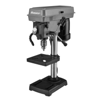
Specifications
Electrical Rating 120VAC / 60 Hz / 2.3 A
Spindle Speeds
5 Speeds: 750, 1100,
1500, 2100, 3200 RPM
Throat Depth 4″ (8″ Max Swing)
Table Tilt 45º left and right
Table Swing Around Column 360°
Spindle Stroke 2″
Chuck Taper JT33
Chuck Capacity 1/2″ (13 mm)
Setup - Before Use
Read the ENTIRE IMPORTANT SAFETY INFORMATION section at the beginning of this
manual including all text under subheadings therein before set up or use of this product.
TO PREVENT SERIOUS INJURY FROM ACCIDENTAL OPERATION:
Turn the Power Switch of the tool off remove the Safety Key, and unplug the tool
from its electrical outlet before performing any procedure in this section.
Note: For additional information regarding the parts listed in the following pages,
refer to the Assembly Diagram near the end of this manual.
Mounting
Secure the tool to a supporting structure before use.
Before assembly, bolt the Base to a flat, level,
solid workbench capable of supporting the
weight of the drill press and any workpieces.
Verify that installation surface has no hidden
utility lines before drilling or driving screws.
Assembly
Column to Base
1. Place Column Base (2) onto the Base (1) and align
holes in the Column Base with holes in the Base.
2. Attach using Hex Bolt (3) in each hole
through the Column and into the Base.
Column (4)
Base (1)
Column
Base (2)
Bolt (3)