Page 8 For technical questions, please call 1-888-866-5797. Item 59583
SAFETY OPERATION MAINTENANCESETUP
Operating Instructions
Read the ENTIRE IMPORTANT SAFETY INFORMATION section at the beginning of this
manual including all text under subheadings therein before set up or use of this product.
Tool Set Up
TO PREVENT SERIOUS INJURY FROM ACCIDENTAL OPERATION:
Turn the Power Switch of the tool off, remove the Safety Key, and unplug the tool
from its electrical outlet before performing any procedure in this section.
TO PREVENT SERIOUS INJURY:
DO NOT OPERATE WITH ANY GUARD DISABLED, DAMAGED, OR REMOVED.
Moving guards must move freely and close instantly.
Performing a Test Run
1. Place the Belt (205) into its lowest position.
(For instructions on Belt movement, refer
to Adjusting Speed on page 10.)
2. Pull out Indexing Pin Knob (21) and rotate
so that Detent is seated on the Roll Pin.
3. Turn Speed Dial (200) fully counterclockwise.
4. Connect machine to power supply.
5. Set Directional Switch (200) to FOR (forward)
position. Pull out on Power Switch (200) to
start Spindle (33), and slowly turn Speed Dial
clockwise. The Digital Readout (75) will light up,
and Spindle will rotate down toward front of Lathe.
6. Turn Speed Dial fully counterclockwise.
7. Push in Power Switch to OFF position.
8. Set Directional Switch to REV (reverse)
position, set Power Switch to ON position,
then slowly turn Speed Dial clockwise.
9. When operating correctly, machine will run
smoothly with little to no vibration or rubbing noises.
Spindle should rotate up toward rear of Lathe.
10. Turn machine off.
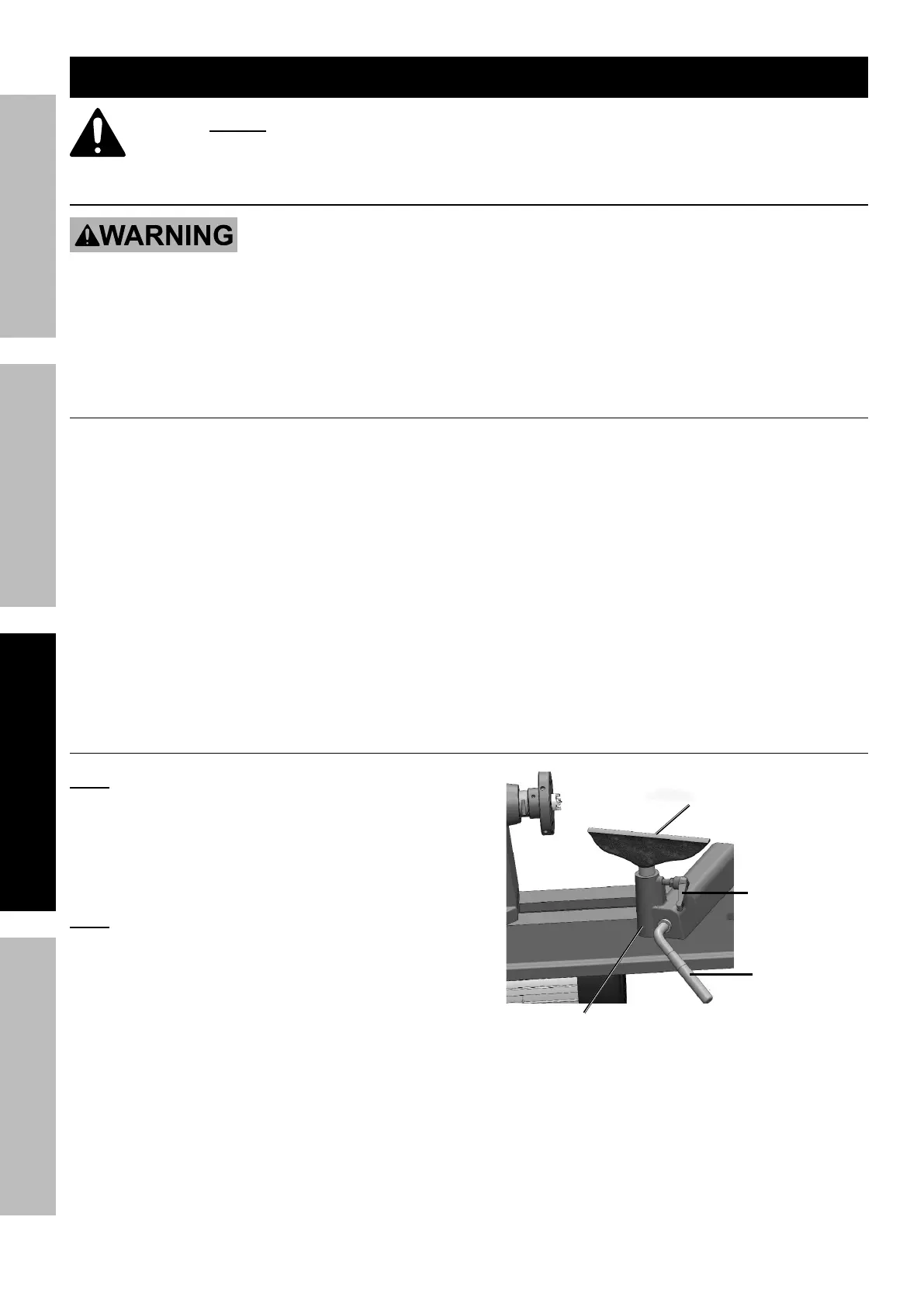
Tool Rest Adjustment
Note: Adjustments to the Tool Rest can be
made based on the work being done.
1. The Tool Rest Locking Lever (207) locks Tool Rest
Base (208) in position. Loosen the Lever to slide
Tool Rest Base along lathe bed. Tighten Lever
firmly when Tool Rest is properly positioned.
Note: There is a nut underneath the Tool Rest
Base that should be tightened periodically to
allow the Locking Lever to tighten properly.
2. Loosen the Tool Rest Locking Handle (59)
to position Tool Rest at a desired angle
or height. Tighten Handle firmly when
Tool Rest is properly positioned.
Tool Rest (209)
Locking
Handle (59)
Locking
Lever (207)
Tool Rest Base (208)