GAS CONNECTION
This appliance shall be installed only by authorised
personnel and in accordance with the manufacturer’s
installation instructions, local gas tting regulations,
municipal building codes, water supply regulations,
electrical wiring regulations, AS 5601 - Gas Installations
and any other statutory regulations.
The appliance is adjusted to work at gas indicated on
the label which is applied on the glass-window of the
oven door and on the cooker packing.
Installation for Natural gas
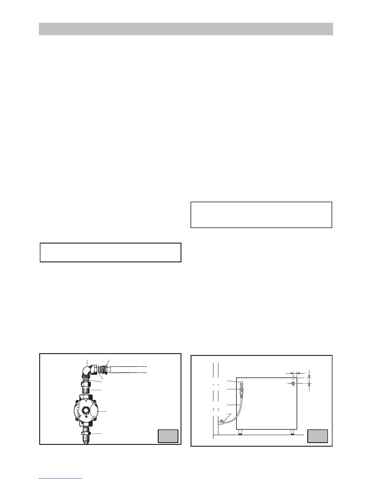
Connected regulator (B) to tting (A) which is then
tted to elbow (F). Ensure arrow on regulator point
in the direction shown. Fitting (D) to be supplied by
installer (g. 17). Adjust regulator to give test-point
pressure given on data label and on page 27, with one
large or one medium burner alight at maximum.
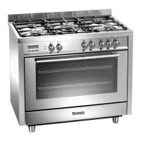
Position of Regulator (g. 17)
If stove is to be installed on legs, a gas pipe between
tting (A) and (B) will allow location of the regulator (B)
underneath the stove for adjustment and maintenance.
If stove is installed on it’s base, the regulator should be
tted at rear of stove on tting (E) for maintenance and
adjustment.
Note: When the regulator is tted at the rear of
the cooker at least 60 mm clearance is required.
Installation using exible connection
As an option, the cooker may be installed with a
exible connection hose, which complies with AS/
NZS 1869 (AGA Approved), 10 mm ID, class B or
D, Minimum 1000 mm - Maximum 1200 mm, as an
alternative connection.
• All cookers offer left or right hand connection. The
manifold has a at air over which is inserted a
screw nut male ½” gas (g.18).
• An isolating tap and pressure regulator must be
xed to the rear wall and the exible pipe attached
INSTRUCTIONS FOR THE INSTALLER
18
by means of a union connector.
• The gas connection and isolating tap must be
accessible to a service person or inspector.
• The hose assembly must be installed in accordance
with AS5601 for a high level connection. The hose
should not be subjected to abrasion, kinking or
permanent deformation and should be able to be
inspected along its entire length. Unions compatible
with the hose ttings must be used and connections
tested for gas leaks. The xed consumer piping
outlet should be at approximately the same height as
the cooker connection point, pointing downwards.
•
The hose should be clear of the oor when the
cooker is in the installed position. The anti-tilting
chain supplied should be anchored to the lower
hook xed to the wall so that the chain prevents
strain on the hose connections when the cooker is
pulled forward.
ELECTRICAL CONNECTION
The electrical connection must be carried out in
accordance with the current standards and laws
in force and by an authorised electrician.
•
Warning this appliance must be earthed.
• Connection to the electricity supply must be made
by an authorised electrician to a suitable isolating
switch in accordance with the requirements of SAA
Wiring Rules, AS/NZS 3000.
• A cable of the correct rating must be used (see
Electrical components).
• Means of disconnection shall be provided in the
xed wiring in accordance with the Australian wiring
rules.
• Remember that the earth wire must be longer
than the phase wires.
• Note: The power supply cable must be positioned
so that no part of cable can come into contact with
any surface which could reach temperatures in
excess of 75 K.