Installation
Basic Supply Unit BUG 622, 623 39
Baumüller Nürnberg GmbH 5.94034.07a
5.5.2 Control terminals
y All control voltages applied externally must comply with the regulations for PELV or SELV
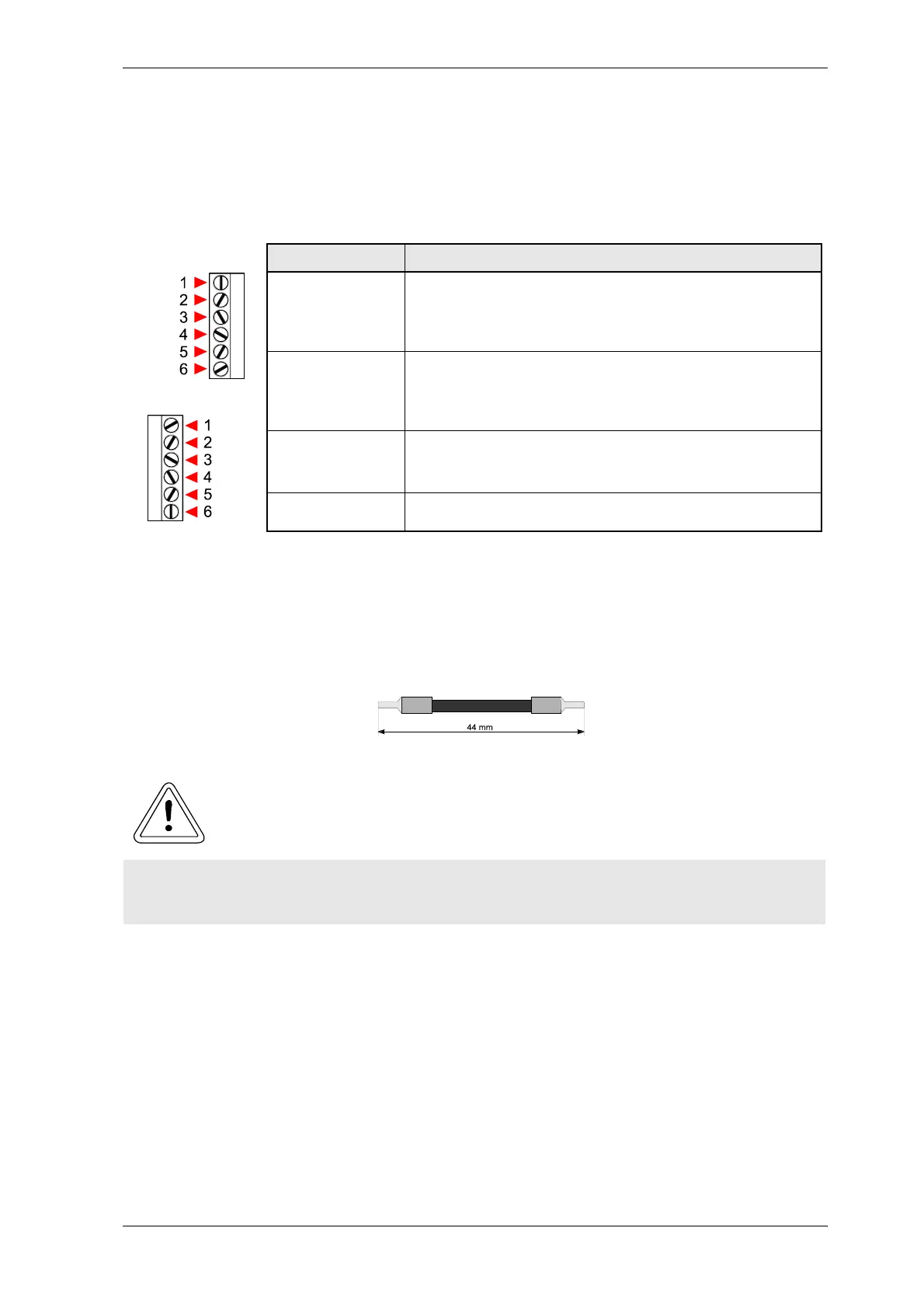
y Sub-unit terminal X99A/X99B
All terminals are connected to each other. Because of this they can be used as BUS-connection from
one Baumüller unit to the other.
The signals can be executed as a bus connection, due to the connection of X99A with X99B of the next
unit in the line.
Recommended connection lead length 44 mm:
X 99 A
X 99 B
Terminal no. Assignment
1, 2 + 24 V (PELV)
Terminal for power supply to the units,
both terminals internally bypassed,
2nd terminal with power supply current > 10 A
3, 4 Ground 24 V (PELV)
Terminal for power supply to the units,
both terminals internally bypassed,
2nd terminal with power supply current > 10 A
5 Ready for use, internal (PELV)
Ready for use message from the supply
converter to all units attached to the DC link.
6
Reserve (PELV)
WARNING
A maximum current greater than 10 A per single terminal may cause damage to the equipment.
If higher currents are needed do build a multiple feeder system.