SUPPLEMENTARY INSTRUCTIONS
FOR THE INSTALLER
21
• Paper boiler template
• 8 mm wall plugs and hooks
The other components in the kit supplied with the wall-mounted boiler and in the COMBI kit must be xed to the COMBI
tting template
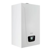
4. BOILER INSTALLATION
Installation must be done taking account of making maintenance easier
. It is necessary to evaluate the weight that the
entire appliance exerts on the oor, taking account of the weight of the water contained in the heater as well.
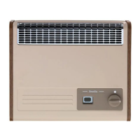
Keep a clearance at the back of 100 mm. Use the adjustable feet to compensate for any unevenness of the oor
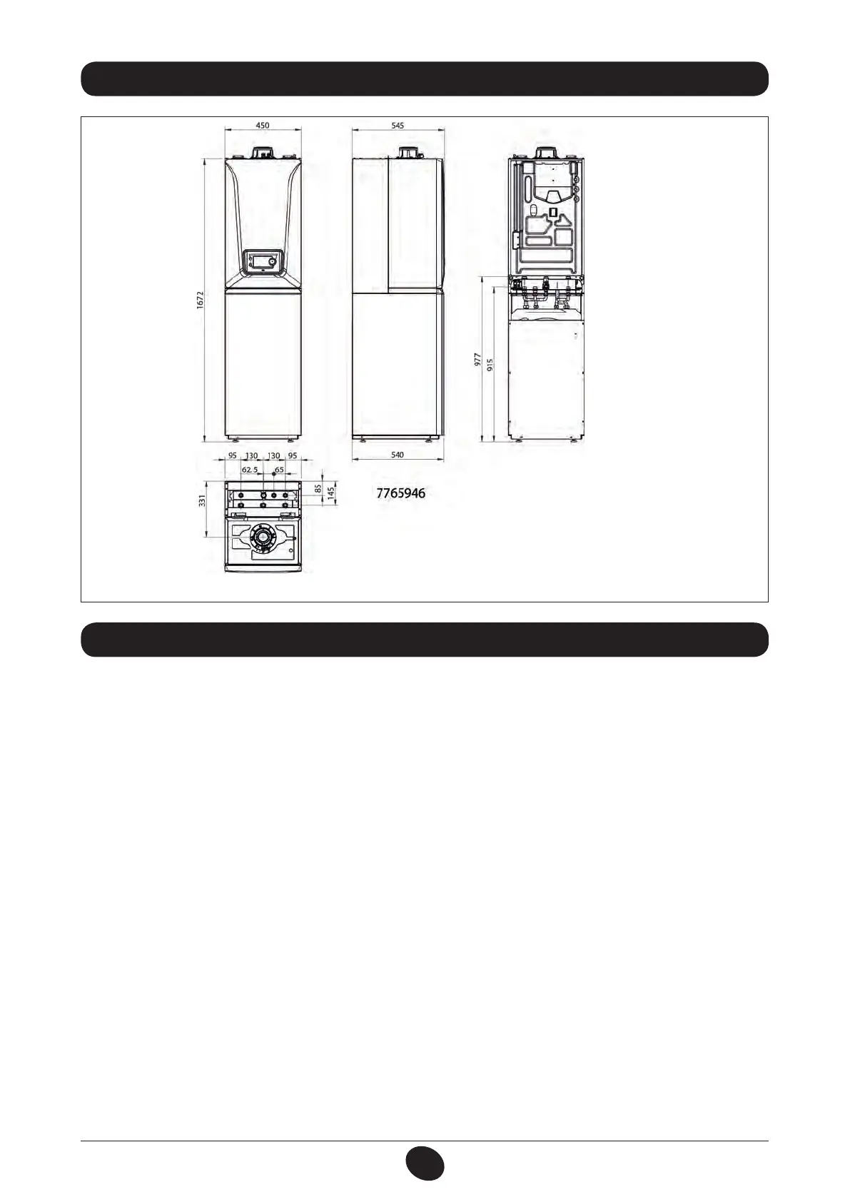
After determining the exact position of the appliance, trace out the axes of the pipes with the aid of the paper template
supplied with the Combi unit. The template must be hung on the wall at a height of 1672 mm.
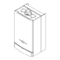
Outfit included in the wall-mount boiler packing (N.B.: not to be used for this application)
3. APPLIANCE DIMENSIONS
Outfit included in the Combi unit
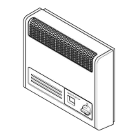
• Paper Modulo unit template
• Domestic hot water outlet pipe
• Seals
• Nipple G 3/4”
• Condensation runoff pipe with clamps.
Install the system starting from the position of the water and gas connections located in the bottom
crosspiece of the connections template.
Key
A boiler delivery G3/4” M
B boiler return G3/4” M
C gas supply pipe G3/4” M
E Domestic water inlet G1/2” M
F Domestic hot water outlet G1/2” M
G Domestic hot water recirculation G 1/2” M
H Flue condensation runoff
I Relief valve outlet
Appliance dimensions
 Loading...