52
18.0 Fault Finding
© Baxi Heating UK Ltd 2013
Temperature sensors faulty.
Cold resistance approximately
10kì @ 25° C (DHW and CH sensors)
20kì @ 25° C (Flue sensor)
(resistance reduces with increase in temp.)
NO
E
Replace sensor
Gas at burner
Ensure gas is on and purged
Replace PCB
Replace gas valve
PCB - X3 connector is 230V AC across
terminals 1 & 2
YES
NO
NO
F
Replace PCB
Check and correct if necessary
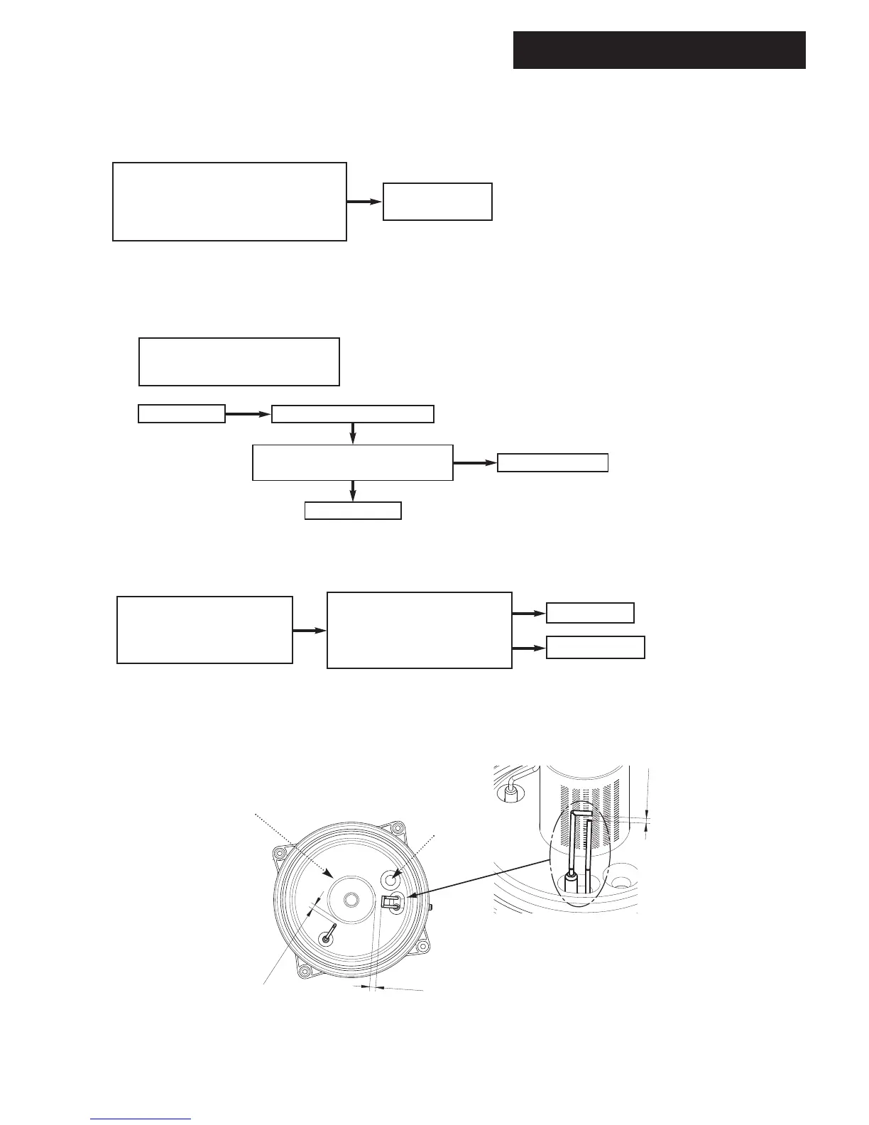
1. Ignition electrode and lead
2. Electrode connection
3. Spark gap and position
Voltage at PCB - X2 connector is at
least 100V DC across terminals 2 & 5
(Note: from multimeter connect
‘common’ to 2 & ‘volt’ to 5)
Check wiring
YES
NO
Replace igniter
YES
G
Check and correct the connection of the
tube between the venturi and gas valve
1.
2.
7.5
±
1
4
±
0.5
1
0
±
1
Spark Ignition
Electrode
Sensing
Electrode
Electrode Position
Viewing Window
Burner
 Loading...