53
© Baxi Heating UK Ltd 2013
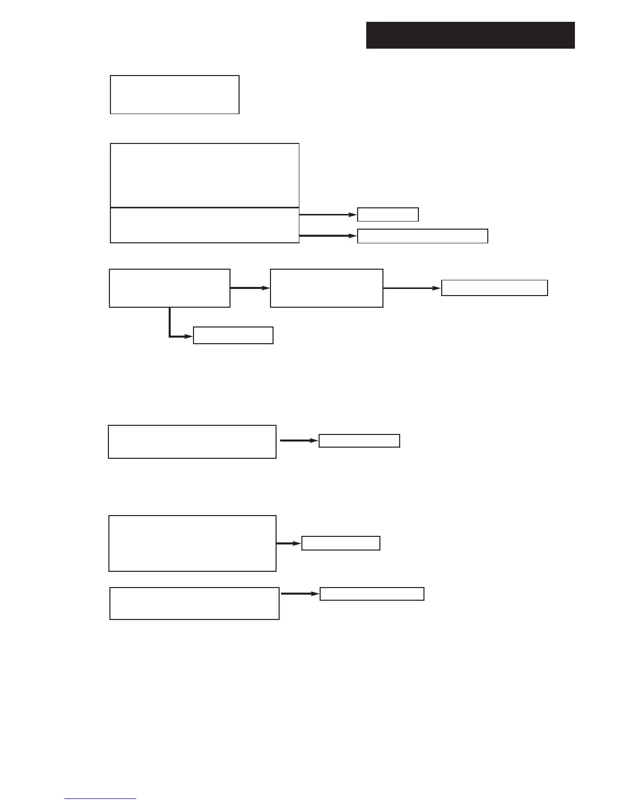
18.0 Fault Finding
Check and correct if necessary
1. The mechanical set of the gas valve
(CO2 values - see instruction)
2. Flame sensing electrode and lead connections
3. Flame sensing electrode position
Flame current should be more than 0.5 ¬ A
Replace PCB
Replace PCB
YES
YES
Replace flame sensing electrode
NO
Check supply pressure at the
gas valve:-
Minimum 17mbar
H
Replace safety thermostat
YES
NO
Overheat thermostat operated or
faulty, i.e. continuity across
thermostat terminals
Allow to cool. Continuity
across thermostat terminals
more than 1.5 ohm
I
J
K
Fan connections correct at fan.
PCB - X401 connector terminals 5,6,7 & 8
1.
YES
Replace fan
Temperature sensors faulty.
Cold resistance approximately
10kì @ 25° C (CH sensor)
20kì @ 25° C (Flue sensor)
(resistance reduces with increase in temp.)
NO
Replace sensor
YES
If pump is running the heat exchanger could be
obstructed
Replace heat exchanger
1.
2.
1.
2.
1.
 Loading...