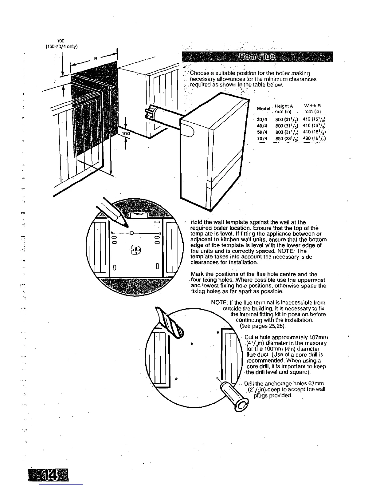
100
(150-70/4 only)
Choose a suitable position for the boiler making
necessary allowances for the minimum clearances
required as shown in the table below.
Model
Height A
mm On)
.
Width B
mm (in)
30/9
800 (31i/2)
410
(181/8)
40/4
8C0(31'/2)
410
(151/8)
50/4
800 (311/2)
410
(161/8)
70/4
850 (331/2)
480
(187/8)
Hold the wall template against the wall at the
required boiler location. Ensure that the top of the
template is level. If fitting the appliance between or.
adjacent to kitchen wall units, ensure that the bottom
edge of the template is level with the lower edge of
the units and is correctly spaced. NOTE: The
template takes into account the necessary side
clearances for installation.
Mark the positions of the flue hole centre and the
four fixing holes. Where possible use the uppermost
and lowest fixing hole positions, otherwise space the
fixing holes as far apart as possible.
NOTE: If the flue terminal is inaccessible from
outside the building, it is necessary to fix
the internal fitting kit in position before
continuing with the installation.
(see pages 25,26).
• Cut a hole approximately 107mm
(41/ in) diameter in the masonry
for the 100mm (4in) diameter
flue duct. (Use of a core drill is
recommended. When using a
core drill, it is important to keep
the drill level and square).
Drill the anchorage holes 63mm
(2
1
/,in) deep to accept the wall
plugs provided.
 Loading...