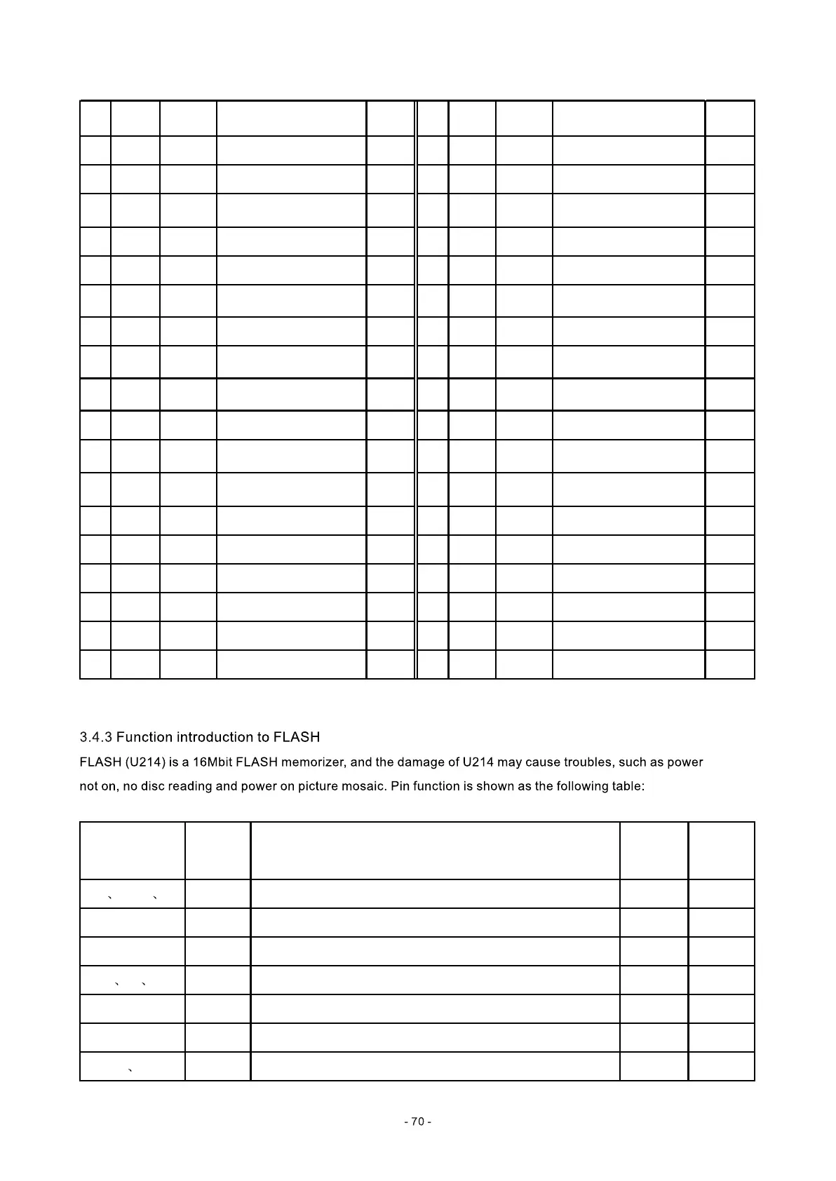
Pin Name
Data
direction
Function
Voltage
(V)
Pin Name
Data
direction
Function
Voltage
(V)
10 DQ5 I/O Data bus 0.7 37 CKE I Clock enable signal 1.22
11 DQ6 I/O Data bus 0.45 38 CLK I System clock input 1.68
12 VSSQ Ground 0 39 UDQM I
Data in/out screen-
shielded signal
2.42
13 DQ7 I/O Data bus 0.8 40 NC Blank pin 0.01
14 VDD 3.3V power supply 3.14 41 VSS Ground 0.01
15 LDQM I
Data in/out screen-
shielded signal
2.46 42 DQ8 I/O Data bus 0.6
16 WE I Write control signal 3.17 43 VDDQ 3.3V power supply 3.19
17 CAS I
Line address gating
signal
3.01 44 DQ9 I/O Data bus 0.91
18 RAS I
Row address gating
signal
3.13 45 DQ10 I/O Data bus 0.8
19 CS I Chip selection signal 2.95 46 VSSQ Ground 0.01
20 SD-BS0 I
Section address 0 gating
signal
1.8 47 DQ11 I/O Data bus 0.79
21 SD-BS1 I
Section address 1 gating
signal
2 48 DQ12 I/O Data bus 1.16
22 MA10 I Address bus 0.04 49 VDDQ 3.3V power supply 3.19
23 MA0 I Address bus 0.36 50 DQ13 I/O Data bus 1.15
24 MA1 I Address bus 0.35 51 DQ14 I/O Data bus 1.24
25 MA2 I Address bus 2.38 52 VSSQ Ground 0.01
26 MA3 I Address bus 1.59 53 DQ15 I/O Data bus 0.68
27 VDD 3.3V power supply 3.19 54 VSS Ground 0.01
Pin Name Function
Voltage
(when no
disc)
Data
direction
1-9 16-25 48
AO-A19 20 bit address bus I
11 WE Write enable signal, low level is effective 3.23V I
12 RESET Reset, low level is effective 3.23V I
10 13 14
NC Blank pin
15 RY/BY Ready/system busy 3.23V O
26 CE Chip enable, low level effective 0V I
27 46
VSS Ground