14
DESCRIZIONE DEI COMANDI
I
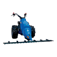
A Contatti Motor-Stop: di colore rosso, arrestano il motore
quando si rilasciano per fine lavoro o per difficoltà; sono
uno su ogni impugnatura del manubrio nella versione a
benzina (fig.4), mentre la versione diesel ha una sola le-
va sull’impugnatura sinistra del manubrio (fig.5).
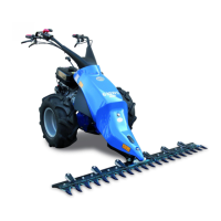
B Leva comando frizione principale (fig.5).
C Manettino comando gas (fig.5).
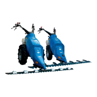
D Leva comando marce: le posizioni delle diverse velocità
sono indicate sul selettore, posto sull’asta di comando
(fig.6).
E Leva innesto presa di forza (fig.6).
F Molla bloccaggio leva frizione (fig.5).
G Leva di regolazione altezza manubrio (fig.6).
H Leva frizione / freno destro (fig.4).
I Leva frizione / freno sinistro (fig.5).
L Leva comando avanzamento e stop; agisce anche come
invertitore del senso di marcia (fig.4).
M Leva per la regolazione laterale del manubrio (fig.4).
CONTROL DESCRIPTION
GB
A Motor Stop contacts; red - these stop the motor when re-
leased after the work has been completed or if problems
arise; there is one on each handgrip of the handlebars
on the petrol version (fig.4) whilst the diesel version has
one single lever on the left handgrip on the handlebars
(fig.5).
B Main clutch lever (fig.5).
C Throttle control lever (fig.5).
D Speed control lever: the location of the different speeds
are shown on the selector which is positioned on the
control lever (fig.6).
E P.T.O. lever (fig.6).
F Spring for clutch lever locking (fig.5).
G Handlebar height adjustment lever (fig.6).
H Right clutch / brake lever (fig.4).
I Left clutch / brake lever (fig.5).
L Forward and stop lever; it is also used to invert direction
(fig.4).
M Lever for lateral adjustment of the handlebars (fig.4).
DESCRIPTION DES COMMANDES
F
A Contacts Moteur-Stop: de couleur rouge, ils arrêtent le
moteur quand ils se relâchent pour fin de travail ou pour
quelques difficultés; ils sont un sur chaque poignée du
volant dans la version essence (fig.4), alors que pour la
version gasoil, il y a un seul levier sur la poignée gauche
du volant (fig.5).
B Levier de commande de l’embrayage principal (fig.5).
C Manivelle commande gaz (fig.5).
D Levier commande des vitesses: les positions des diffé-
rentes vitesses sont indiquées sur le sélecteur, placé sur
la levier (fig.6).
E Levier embrayage prise de force (fig.6).
F Ressort le blocage du levier de l’embrayage (fig.5).
G Levier de réglage de la hauteur du mancheron (fig.6).
H Levier embrayage / frein droit (fig.4).
I Levier embrayage / frein gauche (fig.5).
L Levier de commande et d’arrêt; il agit aussi comme in-
verseur du sens de marche (fig.4).
M Levier pour le réglage latéral du volant (fig.4).
DESCRIPCION DE LOS MANDOS
E
A Contactos Motor-Stop: de color rojo, detienen el motor
cuando se liberan al final del trabajo o debido a dificulta-
des. Hay uno en cada mango del manillar en la versión
de gasolina (fig.4) mientras que la versión diesel tiene
sólo una palanca en el mango izquierdo del manillar (fig.
5).
B Palanca mando embrague principal (fig.5).
C Manguito gas (fig.5).
D Cambio de marchas: las posiciones de las distintas ve-
locidades estan indicadas en el selector, en la palanca
cambio (fig.6).
E Palanca para inserir la toma de fuerza (fig.6).
F Muelle blocaje palanca de embrague (fig.5).
G Palanca de regulación en altura del manillar (fig.6).
H Palanza de embrague / freno derecho (fig.4).
I Palanza de embrague / freno izquierdo (fig.5).
L Palanca mando avance y stop. Actúa también como in-
versor del sentido de marcha (fig.4).
M Palanca para la regulación lateral del manillar (fig.4).
BESCHREIBUNG DER BEDIENUNGSORGANE
D
A Motor-Stopp-Kontakte: in roter Farbe, halten den Motor
an, wenn diese bei Arbeitsende oder bei beschwerli-
chem Betrieb geöffnet werden; in der Benzin-Ausführung
befindet sich je einer am Lenkergriff (Abb.4), in der
Diesel-Ausführung ist hingegen nur ein Hebel am linken
Lenkergriff angebracht (Bild 5).
B Schalthebel der Hauptkupplung (Bild 5).
C Gashebel (Bild 5).
D Geschwindigkeitshebel: die Positionen der verschiede-
nen Geschwindigkeiten sind auf dem Wähler, welcher
auf dem Hebel angebracht ist, angegeben (Bild 6).
E Zapfwellenhebel (Bild 6).
F Feder für die Blockierung des Kupplungshebels (Bild 5).
G Einstellhebel für die Holmenhöhe (Bild 6).
H Rechten Kupplung / Bremse Hebel (Bild 4).
I Linken Kupplung / Bremse Hebel (Bild 5).
L Schalthebel Vorwärts und Stopp; funktioniert auch als
Richtungsumschalter (Bild 4).
M Hebel zur seitlichen Lenkereinstellung (Bild 4).