S2528GX Hardware Installation Manual
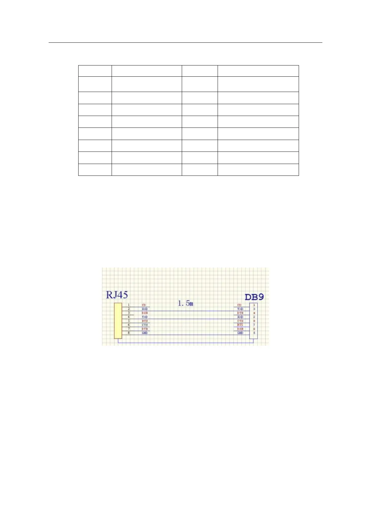
Table 3-1 Definition of the pins of the console port
No. Name Symbol Remarks
1 Carrier Detecting CD No connect
2 Data receiving RXD Input
3 Data-line device ready DSR No connect
4 Data transmitting TXD Output
5 Transmission requesting RTS No connect
6 Response transmitting CTS No connect
7 Data terminal ready DTR No connect
8 Signal ground SG GND
Note:
Because the console port of S2528GX bears no flow control, you need to set Data
flow control to none when using a superior terminal to manage S2528GX
configurations, or the single-pass problem will arise from the superior terminal.
The cable is used to connect the console port of the S2528GX switch and the
outside console terminal device. One end of the cable is a 8-pin RJ45 plug and the
other end is a 9-hole plug (DB9). The RJ45 plug is put into the socket of the console
port on the S2528GX switch. The inner line connection in the cable is shown in figure
3-1. The console cable is numbered as RLC0301.
Figure 3-5 External wiring of the console port
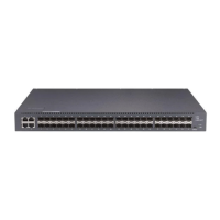
3.3.2 Connecting Gigabit SFP Ports
S2528GX provides 4 gigabit SFP ports. The LEDs of four SFP ports are multiplexed
with TX ports 21-24. The upper LEDs are used to indicate the link state of the port and
the lower LEDs are used to indicate the ACT state of the ports. You can insert the SFP
module and then connect it to other Ethernet terminal devices through the optical fiber
if you want to use the gigabit SFP port.
- 11 -