Do you have a question about the Bdcom S2510-B and is the answer not in the manual?
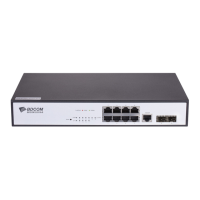
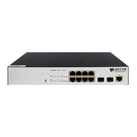
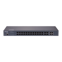
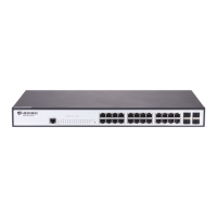
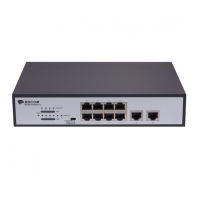
Details the standard configuration of the S2510-B switch, including ports and attributes.
Outlines the technical characteristics and supported standards of the S2510-B switch.
Provides essential cautions for handling and powering on the S2510-B switch to prevent damage.
Details safety principles and notices for operating the S2510-B, including precautions for live working.
Outlines environmental requirements and cabinet configuration guidelines for optimal S2510-B installation.
Specifies the power supply requirements, including voltage range and grounding, for the S2510-B.
Lists the necessary tools and devices required for the installation of the S2510-B switch.
Outlines the step-by-step procedure for installing the S2510-B switch.
Covers methods for installing the S2510-B chassis on a desk and in a cabinet.
Explains how to connect console, SFP, and Ethernet ports on the S2510-B switch.
Lists essential checks to perform after installation but before powering on the S2510-B switch.
Explains the procedure and tools required for safely opening the S2510-B switch chassis.
Details the steps for reassembling and closing the S2510-B switch chassis after maintenance.
Describes the systematic approach to separating faults within the S2510-B system.
Guides on troubleshooting power-related faults by checking power connections and environmental conditions.
Provides steps to diagnose faults related to ports, cables, and network connections on the S2510-B.
Explains the meaning of various LED indicators on the S2510-B switch for status monitoring.
| Switching Capacity | 20 Gbps |
|---|---|
| Forwarding Rate | 14.88 Mpps |
| VLAN Support | Yes |
| MAC address table | 8K |
| Dimensions | 280*180*44 mm |
| Weight | <2.5kg |
| Uplink Ports | 2 x GE SFP |
| Power Supply | 100-240V AC, 50/60Hz |
| Operating temperature | 0°C~45°C |
| Jumbo Frame | 9K bytes |
| Storage Temperature | -40°C~70°C |
| Humidity | 10%~90% non-condensing |
| Ports | 8 x GE RJ45 + 2 x GE SFP |
| Fixed ports | 8 x 10/100/1000Base-T, 2 x 1000Base-X SFP |