Do you have a question about the Bdcom S3756F and is the answer not in the manual?
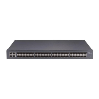
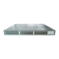
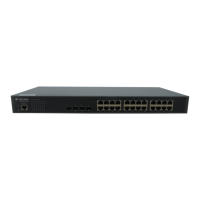
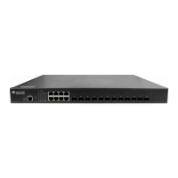
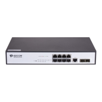
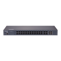
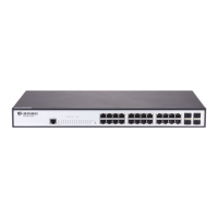
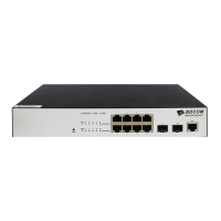
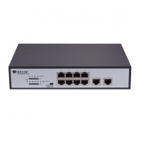
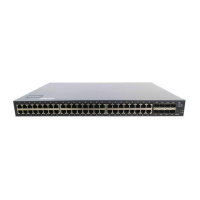
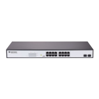
Details the physical ports and indicators on the front of the switch.
Lists supported standards, protocols, and hardware specifications of the switch.
Explains the compliance with RoHS regulations regarding hazardous substances.
Provides critical warnings about power cycling, handling, and port usage to prevent damage.
Encompasses safety principles, notices, and precautions for live working during installation.
Details methods to prevent damage from static electricity during device handling.
Covers environmental, location, cabinet configuration, and power requirements for proper installation.
Lists the necessary tools and devices required for the installation process.
Presents a step-by-step flowchart outlining the switch installation procedure.
Details mounting the switch on a desk or securing it within a cabinet.
Covers connecting the console, 10G SFP+, Gigabit Ethernet TX, and Gigabit SFP ports.
Performs essential checks on power, grounding, and connections after the switch is installed.
Describes the procedure and tools required for safely opening the switch's enclosure.
Details the steps and precautions for reassembling the switch enclosure.
Explains the systematic approach to isolating faults within the switch subsystems.
Guides on troubleshooting issues related to the power supply and cooling fan.
Provides steps for diagnosing problems with ports, cables, and network connections.
Details the meaning and function of the switch's indicator lights.
| Switch Type | Managed |
|---|---|
| VLANs | 4K |
| Jumbo Frame | 9K |
| Layer | Layer 3 |
| Power Supply | AC 100-240V |
| Storage Temperature | -40°C ~ 70°C |
| Operating Humidity | 10% to 90% non-condensing |
| Storage Humidity | 5% to 95% non-condensing |